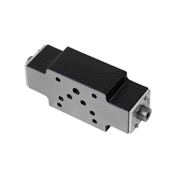
Z2FS seeria topeltdrosseli hüdrauliline kontrollventiil
Üheks hüdrosilindrite tootjaks, tarnijaks ja mehaaniliste toodete eksportijaks pakume hüdrosilindreid ja paljusid teisi tooteid.
Palun võtke meiega ühendust üksikasjade saamiseks.
Post:sales@hydraulic-cylinders.net
Tootja tarnija eksportija hüdrosilindrid.
Z2FS seeria topeltdrosseli hüdrauliline kontrollventiil
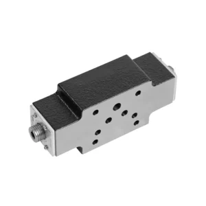
Z2FS-seeria topeltdrosseliga hüdrauliline tagasilöögiklapp on võimas hüdrauliline komponent, mis on loodud hüdraulikasüsteemides erakordse juhtimise ja töökindluse tagamiseks. Oma ainulaadse topeltdrosseliga tagasilöögifunktsiooniga pakub see klapp mitmekülgsust ja täiustatud jõudlust, võimaldades operaatoritel oma hüdraulikarakendusi optimeerida.
Z2FS-seeria topeltdrosseliga hüdrauliline tagasilöögiklapp on asendamatu komponent hüdraulikasüsteemide täpse juhtimise ja töökindluse saavutamiseks. Oma ainulaadse topeltdrosseliga tagasilöögiklapi disainiga pakub see klapp mitmekülgsust, täiustatud juhtimist ja süsteemi stabiilsust. Soovitatavate kasutusmeetodite ja hooldusjuhiste järgimisega saavad operaatorid tagada Z2FS-seeria topeltdrosseliga hüdraulilise tagasilöögiklapi pikaealisuse, töökindluse ja optimaalse funktsionaalsuse. Täienda oma hüdraulikasüsteemi selle erakordse klapiga ja koge paremat jõudlust, mitmekülgsust ja töö efektiivsust.
Z2FS seeria topeltdrosseliga hüdraulilise tagasilöögiklapi peamised omadused:
- Topeltdrosseli kontrollkonstruktsioon:
- Z2FS-seeria ventiilil on spetsiaalne topeltdrosseli tagasilöögiklappide disain, mis ühendab drossel- ja tagasilöögiklappide funktsioonid ühes seadmes.
- See disain pakub täpset voolu reguleerimist ja hoiab ära tagasivoolu, tagades optimaalse jõudluse ja süsteemi efektiivsuse.
- Mitmekülgne rakendus:
- Z2FS-seeria ventiil sobib erinevatele hüdraulikasüsteemidele ja rakendustele, sealhulgas tööstusmasinatele, ehitusseadmetele ja põllumajandusmasinatele.
- Selle mitmekülgsus võimaldab sujuvat integreerimist erinevatesse hüdraulikasüsteemidesse, pakkudes usaldusväärset juhtimist ja toimimist.
- Täiustatud kontroll ja stabiilsus:
- Tänu kahekordse drosselklapi kontrolli funktsioonile pakub see ventiil täpset voolukiiruse juhtimist, võimaldades operaatoritel optimeerida hüdrauliliste ajamite kiirust ja asendit.
- Ventiili võime vältida tagasivoolu suurendab süsteemi stabiilsust ja töökindlust, kaitstes tundlikke komponente võimalike kahjustuste eest.
- Kompaktne ja ruumisäästlik disain:
- Z2FS-seeria ventiilil on kompaktne ja ruumisäästlik disain, mistõttu sobib see ideaalselt piiratud paigaldusruumiga rakenduste jaoks.
- Selle väike jalajälg võimaldab paindlikku paigaldamist ja hõlpsat integreerimist olemasolevatesse hüdraulikasüsteemidesse.
Z2FS seeria topeltdrosseli hüdraulilise klapi parameeter:
| Spetsifikatsioonid | NG6 L4X tüüp | NG6-22 tüüp | ||||||
| Paigaldusasend | / | Valikuline | ||||||
| Voolu suund | / | Ühesuunaline drosselklapp, tagasivool läbi tagasilöögiklapi teises suunas | ||||||
| Vedelik | NBR- ja FKM-tihenditele sobiv mineraalõli | Mineraalõli, fosfaatester | ||||||
| Fosfaatestrid FKM-tihendi jaoks | ||||||||
| Vedeliku temperatuurivahemik | ℃ | -30 kuni +80 (NBR-tihendid) | -20 kuni +80 | |||||
| -20 kuni +80 (FKM tihendid) | ||||||||
| Viskoossusvahemik | mm2/s | 10 kuni 800 | ||||||
| Saastumise aste | Vedeliku maksimaalne lubatud saastumisaste: klass 9. NAS 1638 või 20/18/15, ISO4406 | |||||||
| Nimivool | baar | 315 | / | |||||
| Maksimaalne töörõhk | baar | / | kuni 350 | |||||
| Maksimaalne voolukiirus | L/min | 80 | / | |||||
| Suurus | / | 6 | 10 | 16 | 22 | |||
| Kaal | kg | umbes 1,0 | 0.9 | 3.1 | 4.7 | 8 | ||
Z2FS seeria topeltdrosseliga hüdraulilise ventiili eelised:
NG6 L4X
• Sandwich-tüüpi struktuur
• Paigalduspind vastab standarditele DIN 24340 A ja ISO 4401
• Kasutatakse peavoolu piiramiseks või kahe töötava õliava voolu reguleerimiseks
• Kasutatakse sisselaske- või väljalaskeklapis
NG6-22 tüüp
• Sandwich-tüüpi struktuur
• Paigalduspind vastab standarditele DIN 24340 A ja ISO 4401
• Kasutatakse kahe ajamipordi peapordi vooluhulga või pilootõli vooluhulga piiramiseks
Z2FS-seeria topeltdrosseli hüdraulilise ventiili kasutusmeetod :
- Süsteemi hindamine:
- Alustage hüdraulikasüsteemi nõuete hindamisest, arvestades voolukiirusi, rõhuerinevusi ja süsteemi spetsifikatsioone.
- Tehke kindlaks, kas Z2FS-seeria klapi topeltdrosseli kontrolli funktsioon on konkreetse rakenduse jaoks vajalik.
- Ventiili valik:
- Valige Z2FS-seeria ventiili sobiv variant süsteemi parameetrite ja voolu reguleerimise nõuete põhjal.
- Arvestage selliste aspektidega nagu maksimaalne voolukiirus, rõhuklass ja ühilduvus teiste süsteemi komponentidega.
- Paigaldamine:
- Järgige hoolikalt tootja paigaldusjuhiseid, tagades õige joonduse ja ventiiliühenduste kindlad ühenduskohad.
- Pöörake tähelepanu voolusuuna indikaatoritele, tagades liitmike ja tihendite õige paigaldamise.
- Voolu juhtimise reguleerimine:
- Pärast paigaldamist reguleerige klapi drosselklappi soovitud voolukiiruse saavutamiseks.
- Operaatorid saavad vooluhulga juhtimist hüdrauliliste ajamite konkreetsetele nõuetele vastavaks peenhäälestada, optimeerides jõudlust ja täpsust.
Kuidas hüdraulilised klapitõstukid töötavad?
Hüdrauliline solenoidventiil on elektromehaaniline seade, mis juhib hüdraulilise vedeliku voolu süsteemis. See töötab pingestatud solenoidi põhimõttel, mis loob klapimehhanismi käivitamiseks magnetvälja. Siin on hüdraulilise solenoidventiili tööpõhimõte:
- Ventiili struktuur:
- Hüdrauliline solenoidventiil koosneb tavaliselt klapi korpusest, solenoidmähisest, kolvist või poolmehhanismist ja erinevatest vedeliku voolamise portidest.
- Ventiili korpuses asuvad sisemised komponendid ja vedelikukanalid, mis on vajalikud voolu reguleerimiseks.
- Solenoidmähis ümbritseb kolbi või pooli ja tekitab pinge all magnetvälja.
- Tavaliselt suletud (NC) ja tavaliselt avatud (NO) olekud:
- Hüdraulilised solenoidventiilid saab konfigureerida tavaliselt suletud (NC) või tavaliselt avatud (NO) asendisse, olenevalt nende puhkeolekust.
- NC-konfiguratsioonis on ventiil pingevabalt suletud, blokeerides vedeliku voolu.
- NO-konfiguratsioonis on ventiil pingevabalt avatud, võimaldades vedeliku voolamist.
- Ventiili käivitamine:
- Kui solenoidmähisele rakendatakse elektrivoolu, tekitab see magnetvälja.
- See magnetväli tõmbab kolbi või pooli ligi, pannes selle liikuma vedru või rõhuerinevuse vastu, olenevalt klapi konstruktsioonist.
- Kolvi või pooli liikumine avab või sulgeb klapipordid, kontrollides hüdraulikavedeliku voolu.
- Elektriline juhtimine:
- Hüdraulilise solenoidklapi solenoidmähist juhib tavaliselt elektriskeem, näiteks lüliti või programmeeritav loogikakontroller (PLC).
- Kui vooluring on pingestatud, laseb see voolul läbi solenoidmähise voolata, aktiveerides klapi.
- Kui vooluring on pingevaba, hajub magnetväli ja klapp naaseb puhkeolekusse.
- Voolu suund ja rõhk:
- Hüdraulilistel solenoidventiilidel on vedeliku voolu suuna ja rõhu juhtimiseks erinevad pordikonfiguratsioonid.
- Sõltuvalt klapi konstruktsioonist võivad olla sisselaske-, väljalaske- ja heitgaasiavad.
- Kolvi või pooli asend määrab, millised pordid on ühendatud, võimaldades vedelikul voolata kindlates suundades ja reguleerides rõhutaset.
- Rakendused:
- Hüdraulilisi solenoidventiile kasutatakse laialdaselt erinevates tööstusharudes ja rakendustes, kus on vaja vedeliku voolu täpset juhtimist.
- Neid võib leida tööstusmasinate, ehitusseadmete, põllumajandusmasinate ja autotööstuse hüdraulikasüsteemides.
- Eelised:
- Hüdraulilised solenoidventiilid pakuvad mitmeid eeliseid, sealhulgas kiire reageerimisaeg, täpne juhtimine, kompaktne suurus ja lihtne integreerimine hüdraulikasüsteemidesse.
- Nende elektriline juhtimine võimaldab automatiseerimist ja kaugjuhtimist, suurendades süsteemi tõhusust ja mugavust.
Tehase võimekus ja suutlikkus:
(1) Kokkupanek
Meil on esmaklassiline sõltumatu teadus- ja arendustegevuse montaažiplatvorm. Hüdrosilindrite tootmistöökojas on neli poolautomaatset tõstesilindrite koosteliini ja üks automaatne kallutussilindrite koosteliin, mille kavandatud aastane tootmisvõimsus on 1 miljon tükki. Spetsiaalsete silindrite töökoda on varustatud erinevate spetsifikatsioonidega poolautomaatse puhastusmontaažisüsteemiga, mille kavandatud aastane tootmisvõimsus on 200 000 ja mis on varustatud kuulsate CNC-töötlemisseadmete, mehaanilise töötlemise keskuse, suure täpsusega silindrite töötlemise eriseadmete, robotkeevitusmasina, automaatse puhastusmasina, automaatse silindri kokkupanemise masina ja automaatse värvimise tootmisliiniga. Olemasolevad kriitilised seadmed rohkem kui 300 komplekti (komplekti). Seadmete ressursside optimaalne jaotamine ja tõhus kasutamine tagavad toodete täpsusnõuded ja vastavad toodete kvaliteedinõuetele.


(2) Töötlemine
Töödeldav töökoda on varustatud kohandatud kallutatud rööpse treipingi keskuse, mehaanilise keskuse, kiire lihvimismasina, keevitusroboti ja muude seotud seadmetega, mis suudavad töödelda silindritorusid, mille maksimaalne siseläbimõõt on 400 mm ja maksimaalne pikkus on 6 meetrit.

(3) Keevitamine

(4) Värvimine ja katmine
Väikese ja keskmise suurusega silindri automaatse veepõhise värvipinnakattega liinide abil, et saavutada automaatne robotlaadimine ja mahalaadimine ning automaatne pihustamine, projekteerimisvõimsus 4000 tükki vahetuse kohta;
Meil on ka poolautomaatne suurte balloonide värvimise tootmisliin, mis töötab jõukettaga ja mille projekteerimisvõimsus on 60 kasti ühe vahetuse kohta.


(5) Testimine
Meil on esmaklassilised kontrolliseadmed ja katsestendid, et tagada silindri jõudlus vastavus nõuetele.

Oleme üks parimaid hüdrosilindrite tootjaid. Pakume laia valikut hüdrosilindreid. Pakume ka vastavaid... põllumajanduslikud käigukastid. Oleme eksportinud oma tooteid klientidele üle maailma ja teeninud hea maine tänu meie suurepärasele tootekvaliteedile ja müügijärgsele teenindusele. Me tervitame kliente kodus ja välismaal, et võtta meiega ühendust, et pidada läbirääkimisi äri, vahetada teavet ja teha meiega koostööd!
Hüdrosilindri kasutamine:
