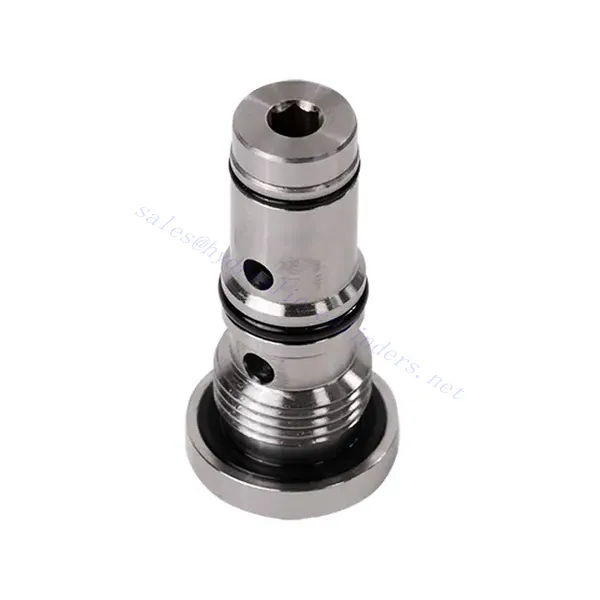
KSF Series Shuttle Hydraulic Valve
KSF Series Shuttle Hydraulic Valve
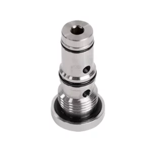
The KSF series shuttle hydraulic valve is a high-performance component designed to enhance fluid flow control in hydraulic systems. With its advanced design and robust construction, this valve offers precise and reliable operation, ensuring optimal system performance.
The KSF series shuttle hydraulic valve is an exceptional solution for fluid flow control in hydraulic systems. With its shuttle valve functionality, robust construction, high flow capacity, and compact design, this valve optimizes performance and ensures efficient utilization of hydraulic power. By following the recommended usage methods and maintenance practices, the KSF series shuttle hydraulic valve delivers reliable operation and extends the lifespan of hydraulic systems. Upgrade your hydraulic system with the KSF series shuttle hydraulic valve and experience enhanced fluid flow control for improved overall system performance.
KSF Series Shuttle Hydraulic Valve Key Characteristics:
- Shuttle Valve Functionality:
- The KSF series valve incorporates a shuttle valve design to divert hydraulic fluid flow between two circuits.
- It enables the selection of the circuit with higher pressure, ensuring efficient utilization of hydraulic power and preventing pressure imbalances.
- Vankka rakenne:
- Built with durable materials, the KSF series shuttle hydraulic valve is designed to withstand high-pressure environments and demanding operating conditions.
- Its robust construction ensures longevity and reliability, minimizing downtime and maintenance costs.
- Suuri virtauskapasiteetti:
- The KSF series valve offers a high flow capacity, allowing for efficient transfer of hydraulic fluid between circuits.
- It minimizes pressure drops, ensuring maximum power delivery and system performance.
- Kompakti ja monipuolinen muotoilu:
- The valve’s compact design makes it suitable for installations with limited space or weight constraints.
- Its versatility allows easy integration into various hydraulic systems, including industrial machinery, mobile equipment, and power units.
KSF Series Shuttle Hydraulic Valve Parameter:
| Koko | NG6 | NG10 | |
| Nesteen lämpötila-alue | ℃ | -30 to +80 (NBR seals) | |
| -20 - +80 (FKM-tiivisteet) | |||
| Viskositeettialue | mm2/s | Suositus 30-80, lupa 20-380 | |
| Maks. käyttöpaine | baari | 350 | |
| Maks. virtausnopeus | L/min | 40 | 60 |
| Paino | kg | 0.5 | 0.8 |
| Neste | Mineraaliöljy, joka sopii NBR- ja FKM-tiivisteille | ||
| Fosfaattiesteri FKM-tiivisteelle | |||
| Saastumisaste | Suurin sallittu nesteen kontaminaatioaste: Luokka 9. NAS 1638 tai 20/18/15, ISO4406 | ||
KSF Series Shuttle Hydraulic Valve Advantages:
• Seal without leakage
• Cartridge structure for oil block installation
Usage Method Of KSF Series Shuttle Hydraulic Valve:
- Järjestelmäanalyysi:
- Before installation, perform a comprehensive hydraulic system analysis to determine specific requirements and operating parameters.
- Consider factors such as flow rates, pressure ratings, and compatibility with the KSF series shuttle hydraulic valve.
- Venttiilin valinta:
- Choose the appropriate KSF series valve variant based on the system’s requirements and specifications.
- Ota huomioon tekijät, kuten virtauskapasiteetti, painearvot ja yhteensopivuus muiden järjestelmäkomponenttien kanssa.
- Asennus:
- Follow the manufacturer’s instructions for properly installing the KSF series shuttle hydraulic Valve in the hydraulic system.
- Ensure a secure fit, proper alignment with the fluid flow path, and adequate sealing to prevent leaks.
- Circuit Connection:
- Connect the inlet and outlet ports of the valve to the corresponding circuits that require fluid diversion.
- Ensure proper identification and connection of the high-pressure circuit and low-pressure circuit.
Miten hydraulinen virtauksen säätöventtiili toimii?
Hydraulinen virtauksen säätöventtiili on laite, jota käytetään hydraulinesteen nopeuden säätämiseen ja ohjaamiseen hydraulijärjestelmässä. Sen avulla käyttäjä voi säätää nesteen virtausnopeutta, mikä estää hydraulisten toimilaitteiden nopeuden tai ohjaa energiansiirron nopeutta. Tässä on selitys siitä, miten hydraulinen virtauksen säätöventtiili toimii:
- Venttiilin rakenne:
- Hydraulinen virtauksen säätöventtiili koostuu tyypillisesti venttiilirungosta, jossa on tulo- ja poistoaukot, liikkuvasta kelasta tai lautasventtiilistä ja käyttömekanismista.
- Venttiilirunko sisältää sisäisiä kanavia ja kammioita, jotka säätelevät hydraulinesteen virtausta.
- Nesteen virtausreitit:
- Virtauksen säätöventtiilissä on tuloaukko, joka on kytketty hydrauliseen virtalähteeseen, kuten pumppuun, ja lähtöaukko, joka on kytketty hydrauliseen toimilaitteeseen tai muuhun komponenttiin.
- Venttiili tarjoaa nesteelle erilaisia virtausreittejä, mikä mahdollistaa sen ohjaamisen ja säätämisen.
- Kela tai lautanen:
- Venttiilirungossa on liikkuva kela tai lautasventtiili, joka säätelee hydraulinesteen virtausta.
- Kela voi liukua venttiilirungon sisällä, kun taas lautasventtiili voi liikkua lineaarisesti tai pyöriä avatakseen tai sulkeakseen tiettyjä kanavia.
- Käyttömekanismi:
- Hydraulisia virtauksen säätöventtiilejä voidaan käyttää manuaalisesti, sähköisesti tai muilla tavoin riippuen erityisistä suunnittelu- ja sovellusvaatimuksista.
- Manuaalinen käyttö tarkoittaa kahvan, nupin tai vivun säätämistä kelan tai poppetin asettamiseksi.
- Sähköisessä toiminnassa käytetään solenoideja, jotka vastaanottavat sähköisiä signaaleja kelan tai venttiilin siirtämiseksi, mikä mahdollistaa kauko-ohjauksen ja automatisoinnin.
- Venttiilien asennot:
- Hydraulisella virtauksen säätöventtiilillä on tyypillisesti useita asentoja, jotka kela tai lautasventtiili voi ottaa, ja joista jokainen vastaa tiettyä virtausnopeutta.
- Venttiilissä voi olla useita esiasetettuja asentoja tai se voi tarjota jatkuvaa säätöä virtausnopeuden hienosäätöä varten.
- Kun kela tai lautasventtiili siirtyy, se kohdistuu tiettyihin kanaviin avaamalla tai sulkemalla niitä nesteen virtauksen hallitsemiseksi.
- Virtauksen säätö:
- Säätämällä kelan tai lautasventtiilin asentoa käyttäjä voi säätää virtauskanavien kokoa ja siten hydraulinesteen virtausnopeutta.
- Kun kanavat ovat täysin auki, neste virtaa vapaasti, mikä mahdollistaa maksimaalisen virtausnopeuden.
- Kanavien osittainen sulkeminen rajoittaa virtausta, mikä vähentää virtausnopeutta ja säätelee hydraulisten toimilaitteiden nopeutta.
- Paineen kompensointi:
- Joissakin hydraulisissa virtauksen säätöventtiileissä on paineenkompensointimekanismeja, jotka ylläpitävät tasaista virtausnopeutta järjestelmän paineen muutoksista huolimatta.
- Nämä mekanismit varmistavat, että haluttu virtausnopeus säilyy, vaikka järjestelmässä olisi vaihteluita kuormituksessa tai paineessa.
Tehtaan kapasiteetti ja kapasiteetti:
(1) Kokoonpano
Meillä on ensiluokkainen riippumaton tutkimus- ja kehitystyön kokoonpanoalusta. Hydraulisylinterien tuotantopajassa on neljä puoliautomaattista nostosylinterin kokoonpanolinjaa ja yksi automaattinen kallistussylinterin kokoonpanolinja, joiden suunniteltu vuotuinen tuotantokapasiteetti on 1 miljoona kappaletta. Erikoissylinterin työpaja on varustettu erilaisilla eritelmillä puoliautomaattisen puhdistusasennuksen kokoonpanojärjestelmällä, jonka suunniteltu vuotuinen tuotantokapasiteetti on 200 000, ja se on varustettu kuuluisilla CNC-työstölaitteilla, työstökeskuksella, korkean tarkkuuden sylinterin käsittelyyn tarkoitetuilla erityislaitteilla, robottihitsauskoneella, automaattisella puhdistuslaitteella, automaattisella sylinterin kokoonpanokoneella ja automaattisella maalaustuotantolinjalla. Olemassa olevat kriittiset laitteet yli 300 sarjaa (sarjaa). Laiteresurssien optimaalinen kohdentaminen ja tehokas käyttö varmistavat tuotteiden tarkkuusvaatimukset ja täyttävät tuotteiden laatuvaatimukset.


(2) Koneistus
Työstöpaja on varustettu räätälöidyllä kaltevalla kiskosorvauskeskuksella, työstökeskuksella, suurnopeus-hiontakoneella, hitsausrobotilla ja muilla vastaavilla laitteilla, joilla voidaan käsitellä sylinteriputkia, joiden sisähalkaisija on enintään 400 mm ja enimmäispituus on 6 metriä.

(3) Hitsaus

(4) Maalaus ja pinnoitus
Pienillä ja keskisuurilla sylinterin automaattisilla vesipohjaisilla maalipinnoituslinjoilla automaattisen robotin lastaus- ja purku- ja automaattisen ruiskutuksen saavuttamiseksi, suunnittelukapasiteetti on 4000 kappaletta vuorossa;
Meillä on myös puoliautomaattinen maalauslinja suurille sylintereille, joka toimii voimaketjulla ja jonka suunnittelukapasiteetti on 60 laatikkoa työvuorossa.


(5) Testaus
Meillä on ensiluokkaiset tarkastustilat ja testialustat, joilla varmistetaan, että sylinterin suorituskyky täyttää vaatimukset.

Olemme yksi parhaista hydraulisylintereiden valmistajista. Voimme tarjota kattavia hydraulisylintereitä. Tarjoamme myös vastaavia maatalousvaihteistotOlemme vieneet tuotteitamme asiakkaille maailmanlaajuisesti ja ansainneet hyvän maineen erinomaisen tuotelaadun ja huoltopalvelumme ansiosta. Toivotamme tervetulleeksi asiakkaat kotimaassa ja ulkomailla ottamaan meihin yhteyttä neuvotellakseen liiketoimista, vaihtaakseen tietoja ja tehdä yhteistyötä kanssamme!