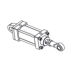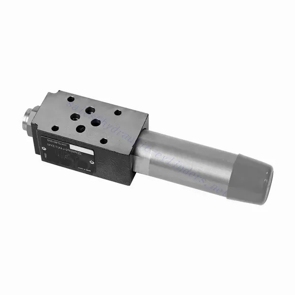
ZDR Series Direct Operated Pressure Reducing Hydraulic Valve
ZDR Series Direct Operated Pressure Reducing Hydraulic Valve
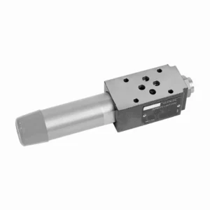
The ZDR series direct-operated pressure-reducing hydraulic valve is a highly efficient and reliable component that provides accurate pressure control in hydraulic systems. With its direct-operated design and exceptional performance, this valve ensures precise pressure reduction to meet specific system requirements.
The ZDR series direct-operated pressure-reducing hydraulic valve is a high-performance solution for precise pressure control in hydraulic systems. With its direct-operated design, accurate pressure control, wide pressure range, and high flow capacity, this valve ensures efficient and reliable pressure reduction while protecting system components. By following the recommended usage methods and maintenance practices, the ZDR series valve delivers reliable performance, extending the lifespan of hydraulic systems. Upgrade your hydraulic system with the ZDR series direct-operated pressure-reducing hydraulic valve and experience optimal pressure control for enhanced system efficiency and productivity.
ZDR Series Direct Operated Pressure Reducing Hydraulic Valve Key Characteristics:
- Suorakäyttöinen suunnittelu:
- The ZDR series valve features a direct-operated design, which enables it to provide precise pressure control without the need for external pilot circuits.
- This design simplifies installation and reduces complexity in hydraulic systems.
- Tarkka paineensäätö:
- This valve offers exceptional accuracy in pressure control, allowing hydraulic systems to maintain the desired pressure range with high reliability.
- It ensures stable operation and protects sensitive system components from excessive pressure.
- Laaja painealue:
- The ZDR series valve is available in various pressure ranges, making it suitable for diverse hydraulic applications.
- The flexibility in pressure range allows customization to match specific system requirements and optimize performance.
- Suuri virtauskapasiteetti:
- This valve exhibits excellent flow capacity, enabling it to handle high flow rates while maintaining precise pressure control.
- It ensures efficient fluid regulation and uninterrupted system operation, even in demanding applications.
ZDR Series Direct Operated Pressure Reducing Hydraulic Valve Parameter:
| Tekniset tiedot | NG10 | NG16 | ||
| Neste | Mineraaliöljy, joka sopii NBR- ja FKM-tiivisteille | |||
| Fosfaattiesteri FKM-tiivisteelle | ||||
| Nesteen lämpötila-alue | ℃ | -30 to +80 (NBR seals) | ||
| -20 - +80 (FKM-tiivisteet) | ||||
| Viskositeettialue | mm2/s | 10–800 | ||
| Saastumisaste | Suurin sallittu nesteen kontaminaatioaste: Luokka 9. NAS 1638 tai 20/18/15, ISO4406 | |||
| Nominal pressure | baari | 315 | ||
| Maks. käyttöpaine | Port P | baari | 315 | |
| Maks. käyttöpaine | Port A | baari | 315 | 250 |
| Maks. käyttöpaine | Portti Y | baari | Separate and at zero pressure to tank | |
| Paineen asettaminen | Min. | baari | Dependent on the flow (see curves) | |
| Max. | baari | 50; 100; 200; 315 | 50; 100; 200; 250 | |
| Maks. virtausnopeus | L/min | 120 | 220 | |
| Paino | kg | about 6.5 | about 8.8 | |
ZDR Series Direct Operated Pressure Reducing Hydraulic Valve Advantages:
• Sandwich-tyyppinen rakenne
• Asennuspinta standardien DIN 24340 A ja ISO 4401 mukaisesti
• Neljä painealuetta
• Kaksi säätötyyppiä: nuppi, säätöruuvi suojakorkilla
• Painemittariliitännällä
• Valinnainen yksisuuntainen venttiili
Usage Method Of ZDR Series Direct Operated Pressure Reducing Hydraulic Valve:
- Järjestelmäanalyysi:
- Conduct a thorough hydraulic system analysis to determine the specific pressure control requirements.
- Ota huomioon suurin käyttöpaine, haluttu painealue ja virtausnopeudet.
- Venttiilin valinta:
- Select the appropriate ZDR series valve variant based on the system’s pressure control specifications.
- Ota huomioon paineluokitus, virtauskapasiteetti ja yhteensopivuus muiden järjestelmäkomponenttien kanssa.
- Asennus:
- Follow the manufacturer’s instructions to correctly install the ZDR series direct-operated pressure-reducing valve in the hydraulic system.
- Varmista oikea kohdistus ja turvalliset liitännät vuotojen estämiseksi ja suorituskyvyn optimoimiseksi.
- Kalibrointi:
- Calibrate the valve to set the desired downstream pressure.
- Käytä painemittareita tai muita mittauslaitteita venttiilin säätämiseen optimaalisen paineen säätöä varten tarkasti.
How Does A Hydraulic Selector Valve Work?
A hydraulic selector valve, also known as a hydraulic diverter valve or hydraulic control valve, is a device used to direct the flow of hydraulic fluid in a hydraulic system. It allows the operator to control the path of fluid flow by selecting different hydraulic circuits or components to operate. Here’s a breakdown of how a hydraulic selector valve works:
- Venttiilin rakenne:
- A hydraulic selector valve consists of a body with multiple ports and internal passages.
- It typically has an actuating mechanism, such as a lever or a solenoid, to control the movement of the valve spool or poppet.
- Portin kokoonpano:
- A selector valve has multiple ports, usually labeled as A, B, and C, or sometimes referred to as P, T, and A/B/C.
- Port P (Pressure) connects to the hydraulic pump or the high-pressure side of the system.
- Port T (Tank) connects to the hydraulic reservoir or the low-pressure side of the system.
- Ports A, B, and C are the output ports that connect to different hydraulic circuits or components.
- Venttiilien asennot:
- The selector valve has different positions that determine the flow path of the hydraulic fluid.
- Common positions include “A,” “B,” “C,” “AB,” “AC,” and “BC,” depending on the specific valve design.
- Fluid Flow Control:
- When the valve is in the neutral or default position, typically labeled “N,” the fluid flow is blocked, and no flow occurs between any of the ports.
- When the operator actuates the valve by moving the lever or energizing the solenoid, the valve spool or poppet shifts to a different position, enabling fluid flow.
- Flow Path Selection:
- By moving the actuating mechanism, the operator can select the desired flow path.
- For example, when the valve is in position “A,” fluid flows from port P to port A, allowing the hydraulic circuit or component connected to port A to operate.
- Multiple Flow Paths:
- Depending on the specific valve design, a hydraulic selector valve can provide multiple flow paths.
- For instance, in position “AB,” fluid can flow from port P to both ports A and B simultaneously, allowing operation of two separate hydraulic circuits or components.
- Ohjaus ja toiminta:
- The actuating mechanism of the selector valve can be manual, where the operator physically moves a lever or knob, or it can be electric or pneumatic, using solenoids or other control devices.
- Electrically controlled selector valves can be integrated into automated systems or controlled remotely.
- System Flexibility:
- Hydraulic selector valves provide flexibility in system design and operation.
- They allow the operator to switch between different hydraulic circuits or components, facilitating tasks such as equipment positioning, attachment control, or switching between different implements.
Tehtaan kapasiteetti ja kapasiteetti:
(1) Kokoonpano
Meillä on ensiluokkainen riippumaton tutkimus- ja kehitystyön kokoonpanoalusta. Hydraulisylinterien tuotantopajassa on neljä puoliautomaattista nostosylinterin kokoonpanolinjaa ja yksi automaattinen kallistussylinterin kokoonpanolinja, joiden suunniteltu vuotuinen tuotantokapasiteetti on 1 miljoona kappaletta. Erikoissylinterin työpaja on varustettu erilaisilla eritelmillä puoliautomaattisen puhdistusasennuksen kokoonpanojärjestelmällä, jonka suunniteltu vuotuinen tuotantokapasiteetti on 200 000, ja se on varustettu kuuluisilla CNC-työstölaitteilla, työstökeskuksella, korkean tarkkuuden sylinterin käsittelyyn tarkoitetuilla erityislaitteilla, robottihitsauskoneella, automaattisella puhdistuslaitteella, automaattisella sylinterin kokoonpanokoneella ja automaattisella maalaustuotantolinjalla. Olemassa olevat kriittiset laitteet yli 300 sarjaa (sarjaa). Laiteresurssien optimaalinen kohdentaminen ja tehokas käyttö varmistavat tuotteiden tarkkuusvaatimukset ja täyttävät tuotteiden laatuvaatimukset.


(2) Koneistus
Työstöpaja on varustettu räätälöidyllä kaltevalla kiskosorvauskeskuksella, työstökeskuksella, suurnopeus-hiontakoneella, hitsausrobotilla ja muilla vastaavilla laitteilla, joilla voidaan käsitellä sylinteriputkia, joiden sisähalkaisija on enintään 400 mm ja enimmäispituus on 6 metriä.

(3) Hitsaus

(4) Maalaus ja pinnoitus
Pienillä ja keskisuurilla sylinterin automaattisilla vesipohjaisilla maalipinnoituslinjoilla automaattisen robotin lastaus- ja purku- ja automaattisen ruiskutuksen saavuttamiseksi, suunnittelukapasiteetti on 4000 kappaletta vuorossa;
Meillä on myös puoliautomaattinen maalauslinja suurille sylintereille, joka toimii voimaketjulla ja jonka suunnittelukapasiteetti on 60 laatikkoa työvuorossa.


(5) Testaus
Meillä on ensiluokkaiset tarkastustilat ja testialustat, joilla varmistetaan, että sylinterin suorituskyky täyttää vaatimukset.

Olemme yksi parhaista hydraulisylintereiden valmistajista. Voimme tarjota kattavia hydraulisylintereitä. Tarjoamme myös vastaavia maatalousvaihteistotOlemme vieneet tuotteitamme asiakkaille maailmanlaajuisesti ja ansainneet hyvän maineen erinomaisen tuotelaadun ja huoltopalvelumme ansiosta. Toivotamme tervetulleeksi asiakkaat kotimaassa ja ulkomailla ottamaan meihin yhteyttä neuvotellakseen liiketoimista, vaihtaakseen tietoja ja tehdä yhteistyötä kanssamme!