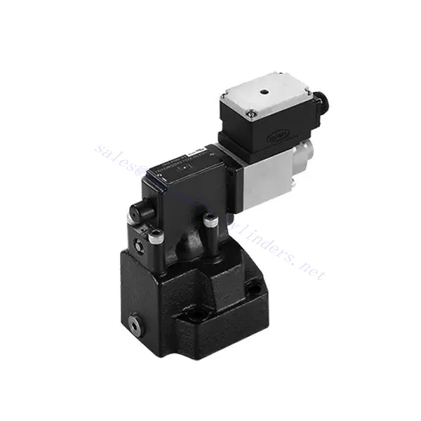
DRE(E)-sarjan proportionaalinen paineenalennushydraulinen venttiili
DRE(E)-sarjan proportionaalinen paineenalennushydraulinen venttiili
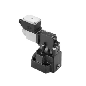
DRE(E)-sarjan proportionaalinen paineenalennushydrauliventtiili on huippuluokan hydrauliikkakomponentti, joka mahdollistaa tarkan paineensäädön hydraulijärjestelmissä. Edistyksellisen proportionaalisen säätöteknologiansa ansiosta tämä venttiili varmistaa optimaalisen suorituskyvyn, tehokkuuden ja turvallisuuden.
DRE(E)-sarjan proportionaalinen paineenalennushydrauliventtiili antaa hydraulijärjestelmille tarkan paineensäädön, paremman tehokkuuden ja laitteiden suojauksen. Edistyksellisen proportionaalisen ohjausteknologiansa ansiosta tämä venttiili varmistaa optimaalisen suorituskyvyn erilaisissa sovelluksissa. Noudattamalla suositeltuja käyttömenetelmiä ja huolto-ohjeita voit maksimoida DRE(E)-sarjan venttiilin hyödyt ja luotettavuuden, mikä parantaa paineensäätöä ja hydraulijärjestelmäsi yleistä suorituskykyä. Päivitä hydrauliikkajärjestelmäsi jo tänään ja koe erinomainen paineensäätö DRE(E)-sarjan proportionaalisella paineenalennushydrauliventtiilillä.
DRE(E)-sarjan proportionaalisen paineenalennushydraulisen venttiilin tärkeimmät ominaisuudet:
- Suhteellinen paineenalennus:
- DRE(E)-sarjan venttiili tarjoaa tarkan ja suhteellisen paineenalennuksen, mikä mahdollistaa dynaamisen hydraulisen paineensäädön.
- Se varmistaa tarkan paineensäädön ja ylläpitää tasaista ja turvallista painetasoa hydraulijärjestelmässä.
- Parannettu järjestelmän tehokkuus:
- Tämä venttiili mahdollistaa tarkan hydraulisen paineen säädön, mikä parantaa järjestelmän tehokkuutta ja vähentää energiankulutusta.
- Ylläpitämällä haluttuja painetasoja se minimoi paineenvaihtelut, optimoi järjestelmän suorituskyvyn ja alentaa käyttökustannuksia.
- Turvallisuus ja laitteiden suojaus:
- DRE(E)-sarjan venttiili toimii suojamekanismina rajoittamalla hydraulijärjestelmän painetta ja suojaamalla laitteita ja käyttäjiä.
- Se estää liiallisen paineen muodostumisen, mikä vähentää komponenttien vaurioitumisen, järjestelmävikojen ja mahdollisten onnettomuuksien riskiä.
- Proportionaalinen ohjaustoiminto:
- DRE(E)-sarjan venttiili tarjoaa proportionaalisen ohjausteknologiansa ansiosta sujuvan ja tarkan paineensäädön.
- Se mahdollistaa reaaliaikaisen paineensäädön, mikä takaa saumattoman integroinnin erilaisiin hydraulijärjestelmiin ja sovelluksiin.
DRE(E)-sarjan proportionaalisen paineenalennushydraulisen venttiilin parametri:
| Yleistä | ||||
| Neste | Mineraaliöljy, joka sopii NBR- ja FKM-tiivisteille | |||
| Fosfaattiesteri FKM-tiivisteelle | ||||
| Nesteen lämpötila-alue | ℃ | -30 - +80 (NBR-tiivisteet) | ||
| -20 - +80 (FKM-tiivisteet) | ||||
| Viskositeettialue | mm2/s | 2,8–380 | ||
| Saastumisaste | Suurin sallittu nesteen kontaminaatioaste: Luokka 9. NAS 1638 tai 20/18/15, ISO4406 | |||
| Maks. käyttöpaine | 315 baaria | |||
| Portit A, B, X | baari | 50; 100; 200; 315 | ||
| Suurin asetuspaine | baari | Virtauksen (Q) osalta katso ominaiskäyrät | ||
| Min. säädettävä paine | =Min. säädettävä paine | |||
| Pienin asetettava paine komentoarvolla 0 | Erillinen ja paineeton säiliöihin | |||
| Paluuöljyn paineliitäntä Y | baari | Paineen asettaminen | Painealue enimmäisturvapaineen rajoissa | |
| Maksimipaineen turvallisuus (portaattomasti säädettävä) | 50 baaria | 10-60+20 baari | ||
| 100 baaria | 10-120+20 baari | |||
| 200 baaria | 10-220+20 baari | |||
| 315 baaria | 10-340+20 baari | |||
| Maksimipaineen turva-asetusehto | Kun nimellispaine on 50 bar, 60 barin ja 80 barin välillä | |||
| Kun nimellispaine on 100 bar, 120 barin ja 140 barin välillä | ||||
| Kun nimellispaine on 200 bar, 220 barin ja 240 barin välillä | ||||
| Kun nimellispaine on 315 bar, 340 barin ja 360 barin välillä | ||||
| Koko | 10 | 25 | 32 | |
| Maks. virtausnopeus | 200 | 400 | 600 | |
| Pilottiöljy (pilottiventtiilille)) | L/min | 0,7–2 | ||
| Lineaarisuus | L/min | ±3,5% | ||
| Toistettavuus | <±2% | |||
| Hystereesi | shimmyn kanssa | ilman shimmyä | ||
| ±1,5% P max (200 Hz, amplitudi 200 mAss) | ±4,5% P maks. | |||
| Kytkentäaika | 30~150 ms (järjestelmästä riippumaton) | |||
| Sähkötiedot | ||||
| Voima | DC | |||
| Solenoidin minimivirta | mA | 100 | ||
| Solenoidin maksimivirta | mA | 800 | ||
| Käämin vastus | 19,5 Ω 20 ℃:ssa, suurin lämmin arvo: 28,8 Ω | |||
| Työskentelytila | Jatkuva | |||
| Ympäristön enimmäislämpötila-alue | +50 ℃ | |||
| Sähköliitäntä | Pistoliitin DIN 43 650/2 +SL/PG11 -standardin mukaisesti | |||
| Eristys DIN 40 050:n mukaisesti | IP65 | |||
| Vahvistin | VT2000 | |||
DRE(E)-sarjan proportionaalisen paineenalennushydraulisen venttiilin edut:
• Käytetään pohjalevyn asennukseen
• Asennuspinta standardien DIN24340 E ja ISO 6264 mukainen
• Käytetään öljypolkujen lohkojen asennuksessa
• Neljä painealuetta
• Korkeimman paineen suojausrakenne (valinnainen)
• Sopiva elektroninen vahvistin tyyppiä VT-2000 (tilattava erikseen)
DRE(E)-sarjan proportionaalisen paineenalennushydraulisen venttiilin käyttötapa:
- Järjestelmän arviointi:
- Arvioi hydrauliikkajärjestelmäsi ja määritä erityiset paineensäätövaatimukset.
- Määritä, onko DRE(E)-sarjan venttiili yhteensopiva järjestelmäsi kanssa sen painealueen, virtauskapasiteetin ja muiden ominaisuuksien perusteella.
- Venttiilin valinta:
- Valitse sopiva DRE(E)-sarjan venttiiliversio järjestelmäparametrien, painealueen ja virtausvaatimusten perusteella.
- Ota huomioon suurin sallittu paineluokitus, vasteaika ja käyttöolosuhteet.
- Asennus:
- Noudata valmistajan asennusohjeita huolellisesti ja varmista venttiilin oikea kohdistus ja tukeva kiinnitys.
- Liitä venttiili hydraulijärjestelmään varmistaen vuotamattomat liitännät ja oikean virtaussuunnan kohdistuksen.
- Paineen säätö:
- Käytä DRE(E)-sarjan venttiilin mukana toimitettua suhteellista ohjaussignaalia tai säätömekanismia halutun paineenalennustason asettamiseksi.
- Säädä venttiiliä asteittain ja seuraa painemittarin lukemia ja järjestelmän vastetta tarkan paineensäädön saavuttamiseksi.
Kuinka säätää hydraulista paineenalennusventtiiliä?
Hydraulisen paineenalennusventtiilin säätö mahdollistaa hydraulijärjestelmän maksimipaineen säätämisen. Tämä on tärkeää järjestelmän eheyden ylläpitämiseksi ja komponenttien vaurioitumisen estämiseksi. Tässä on vaiheittainen opas hydraulisen paineenalennusventtiilin säätämiseen:
- Tunnista paineenalennusventtiili:
- Paikanna järjestelmän hydraulinen paineenalennusventtiili. Se on tyypillisesti sijoitettu hydrauliikkalinjaan tai integroitu jakotukkilohkoon.
- Ymmärrä venttiilin suunnittelu:
- Tutustu käyttämäsi paineenalennusventtiilin erityiseen rakenteeseen. Eri venttiileissä voi olla erilaisia säätömekanismeja, kuten nuppi, ruuvi tai lukkomutteri.
- Halutun paineasetuksen määrittäminen:
- Arvioi hydrauliikkajärjestelmäsi vaatimukset ja määritä haluttu maksimipaine. Ota huomioon järjestelmän tekniset tiedot, kuormitusolosuhteet ja turvallisuusrajat.
- Valmistele järjestelmä:
- Ennen säätöjen tekemistä sammuta hydraulijärjestelmä ja vapauta paine siirtämällä ohjausvipuja edestakaisin tai noudattamalla valmistajan suosittelemia ohjeita.
- Paikanna säätömekanismi:
- Tunnista paineenalennusventtiilin säätömekanismi. Se voi olla nuppi, ruuvi tai lukkomutteri, joka sijaitsee venttiilin rungossa tai sen vieressä.
- Säädä venttiiliä:
- Jos venttiilissä on nuppi tai kahva, käännä sitä myötäpäivään lisätäksesi paineenalennusta tai vastapäivään vähentääksesi sitä. Jos venttiilissä on ruuvi, käännä sitä myötäpäivään lisätäksesi maadoituskorkeutta tai vastapäivään laskeaksesi sitä.
- Tee asteittaisia säätöjä:
- Kun säädät paineenalennusventtiiliä, tee pieniä, vähittäisiä muutoksia välttääksesi äkillisiä tai rajuja paineenvaihteluita. Näin voit hienosäätää järjestelmää ja estää mahdolliset vauriot.
- Tarkkaile järjestelmää:
- Tarkkaile jokaisen säädön yhteydessä hydraulijärjestelmän painemittaria tai ilmaisinta nähdäksesi muutosten vaikutuksen. Varmista, että paine pysyy halutulla alueella.
- Testaa ja varmista:
- Nosta järjestelmän painetta vähitellen ja tarkkaile paineenalennusventtiilin vastetta. Varmista, että se vapauttaa painetta, kun suurin asetettu paine on saavutettu, ja ylläpitää haluttua maksimipainetta.
- Lukitse säätö:
- Kun olet saavuttanut halutun paineasetuksen, kiinnitä säätömekanismi estääksesi tahattomat muutokset. Joissakin venttiileissä voi olla lukitusmutteri tai asetusruuvi, jota voidaan kiristää säädön pitämiseksi paikallaan.
- Dokumentoi säätö:
- Pidä kirjaa säädetystä paineenalennusasetuksesta myöhempää tarvetta ja huoltoa varten. Tämä dokumentaatio auttaa ylläpitämään yhdenmukaisuutta ja helpottaa vianmääritystä.
Tehtaan kapasiteetti ja kapasiteetti:
(1) Kokoonpano
Meillä on ensiluokkainen riippumaton tutkimus- ja kehitystyön kokoonpanoalusta. Hydraulisylinterien tuotantopajassa on neljä puoliautomaattista nostosylinterin kokoonpanolinjaa ja yksi automaattinen kallistussylinterin kokoonpanolinja, joiden suunniteltu vuotuinen tuotantokapasiteetti on 1 miljoona kappaletta. Erikoissylinterin työpaja on varustettu erilaisilla eritelmillä puoliautomaattisen puhdistusasennuksen kokoonpanojärjestelmällä, jonka suunniteltu vuotuinen tuotantokapasiteetti on 200 000, ja se on varustettu kuuluisilla CNC-työstölaitteilla, työstökeskuksella, korkean tarkkuuden sylinterin käsittelyyn tarkoitetuilla erityislaitteilla, robottihitsauskoneella, automaattisella puhdistuslaitteella, automaattisella sylinterin kokoonpanokoneella ja automaattisella maalaustuotantolinjalla. Olemassa olevat kriittiset laitteet yli 300 sarjaa (sarjaa). Laiteresurssien optimaalinen kohdentaminen ja tehokas käyttö varmistavat tuotteiden tarkkuusvaatimukset ja täyttävät tuotteiden laatuvaatimukset.


(2) Koneistus
Työstöpaja on varustettu räätälöidyllä kaltevalla kiskosorvauskeskuksella, työstökeskuksella, suurnopeus-hiontakoneella, hitsausrobotilla ja muilla vastaavilla laitteilla, joilla voidaan käsitellä sylinteriputkia, joiden sisähalkaisija on enintään 400 mm ja enimmäispituus on 6 metriä.

(3) Hitsaus

(4) Maalaus ja pinnoitus
Pienillä ja keskisuurilla sylinterin automaattisilla vesipohjaisilla maalipinnoituslinjoilla automaattisen robotin lastaus- ja purku- ja automaattisen ruiskutuksen saavuttamiseksi, suunnittelukapasiteetti on 4000 kappaletta vuorossa;
Meillä on myös puoliautomaattinen maalauslinja suurille sylintereille, joka toimii voimaketjulla ja jonka suunnittelukapasiteetti on 60 laatikkoa työvuorossa.


(5) Testaus
Meillä on ensiluokkaiset tarkastustilat ja testialustat, joilla varmistetaan, että sylinterin suorituskyky täyttää vaatimukset.

Olemme yksi parhaista hydraulisylintereiden valmistajista. Voimme tarjota kattavia hydraulisylintereitä. Tarjoamme myös vastaavia maatalousvaihteistotOlemme vieneet tuotteitamme asiakkaille maailmanlaajuisesti ja ansainneet hyvän maineen erinomaisen tuotelaadun ja huoltopalvelumme ansiosta. Toivotamme tervetulleeksi asiakkaat kotimaassa ja ulkomailla ottamaan meihin yhteyttä neuvotellakseen liiketoimista, vaihtaakseen tietoja ja tehdä yhteistyötä kanssamme!