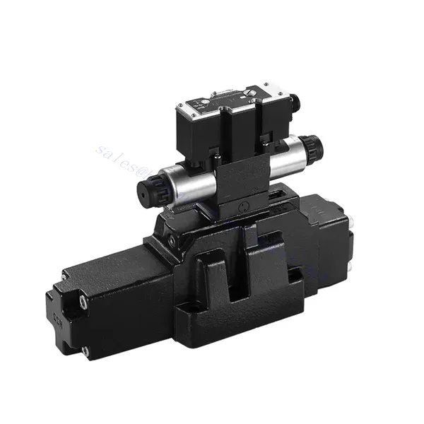
4WRZ/H(E) Series Pilot Operated Proportional Directional Hydraulic Valve
Yhtenä hydraulisylinterien valmistajista, toimittajista ja mekaanisten tuotteiden viejistä tarjoamme hydraulisylintereitä ja monia muita tuotteita.
Ota yhteyttä meihin saadaksesi lisätietoja.
Posti:sales@hydraulic-cylinders.net
Valmistaja toimittaja viejä hydraulisylinterit.
4WRZ/H(E) Series Pilot Operated Proportional Directional Hydraulic Valve
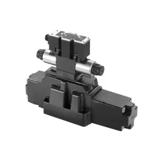
The 4WRZ/H(E) series pilot-operated proportional directional hydraulic valve is a state-of-the-art component designed to provide exceptional precision, control, and efficiency in hydraulic systems. With its advanced pilot-operated proportional control technology, this valve enables accurate flow regulation and seamless directional changes.
The 4WRZ/H(E) series pilot-operated proportional directional hydraulic valve empowers hydraulic systems with precise flow control, versatile directional changes, and energy efficiency. Its pilot-operated proportional control technology ensures accurate and responsive flow adjustment, while the high flow capacity guarantees reliable performance even in demanding applications. By following the recommended usage methods and maintenance guidelines, you can maximize the benefits and longevity of the 4WRZ/H(E) series valve, elevating your hydraulic system to new levels of precision and control. Upgrade your hydraulic setup today and experience the power of the 4WRZ/H(E) series pilot-operated proportional directional hydraulic valve.
4WRZ/H(E) Series Pilot Operated Proportional Directional Hydraulic Valve Key Characteristics:
- Pilot-Operated Proportional Control
- The 4WRZ/H(E) series valve utilizes pilot-operated proportional control technology, allowing precise and proportional flow adjustment based on control signals.
- Tämä ominaisuus varmistaa tarkan ja reagoivan ohjauksen, mikä parantaa järjestelmän suorituskykyä, vähentää energiankulutusta ja lisää tuottavuutta.
- Versatile Directional Control
- Tämä venttiili tarjoaa monipuolisen hallinnan hydraulinesteen suunnalle, joten se sopii monenlaisiin sovelluksiin.
- Se mahdollistaa hydraulisten komponenttien, kuten sylinterien, moottoreiden ja toimilaitteiden, saumattoman aktivoinnin ja deaktivoinnin eri suuntiin, mikä parantaa järjestelmän joustavuutta ja sopeutumiskykyä.
- High Flow Capacity
- The 4WRZ/H(E) series valve is engineered to handle high flow rates, making it ideal for applications that require substantial hydraulic power.
- Sen kestävä rakenne varmistaa luotettavan suorituskyvyn myös vaativissa olosuhteissa ja tarjoaa tasaisen ja tehokkaan virtauksen hallinnan.
- Energiatehokkuus
- By incorporating pilot-operated proportional control, this valve minimizes pressure drops and optimizes energy usage.
- It helps reduce energy consumption, resulting in cost savings and environmental benefits.
4WRZ/H(E) Series Pilot Operated Proportional Directional Hydraulic Valve Parameter:
| GeneraL | |||||||
| Valve type | WRZ | WRZE | |||||
| Asennus | Optional,preferably horizontal | ||||||
| Storage temperature range | ℃ | -20 to +80 | |||||
| Ympäristön lämpötila-alue | ℃ | -20 - +70 | -20 to +50 | ||||
| Paino | NS 10 | kg | 7.8 | 8 | |||
| NS 16 | kg | 13.4 | 13.6 | ||||
| NS 25 | kg | 18.2 | 18.4 | ||||
| NS 32 | kg | 42.2 | 42.4 | ||||
| Hydraulinen (measured with HLPAG.p=100bar : 40 ℃ ± 5 ℃) | |||||||
| Koko | 10 | 16 | 25 | 32 | |||
| Käyttöpaine | Pilot valve | External pilot oil supply | baari | 30 to 100 bar | |||
| Internal pilot oil supply | baari | 100 to 350 with “D3” only | |||||
| Main valve | baari | to 315 | to 350 | to 350 | to 350 | ||
| Return pressure | Port T (Port R) (external pilot oil drain)) | baari | to 315 | to 250 | to 250 | to 150 | |
| Port T (internal pilot oil drain) | baari | to 30 | to 30 | to 30 | to 30 | ||
| Portti Y | baari | to 30 | to 30 | to 30 | to 30 | ||
| Pilot oil volume input signal 0- 100 % | cm3 | 1.7 | 4.6 | 10 | 26.5 | ||
| Pilot oil flow in port X and Y with a stepped input signal 0- 100 % | 3.5 | 5.5 | 7 | 15.9 | |||
| Flow of the main valve | L/min | to 170 | to 460 | to 870 | to 1600 | ||
| Hydraulineste | L/min | Mineral oil (HL, HLP) to DIN 51524 Further fluids on enquiry | |||||
| Hydraulic fluid temperature range | ℃ | -20 to +80(preferably +40 to +50) | |||||
| Viskositeettialue | mm2/s | 20 to 380(preferably 30 to 46) | |||||
| Saastumisaste | Maximum permissible degree of contamination of the pressure fluid is to NAS 1638 or ISO 4406(c) | A filter with a minimum retention rate of βx ≥ 75 is recommended | |||||
| Pilot valve | NAS 1638 class 7 | x=5 | |||||
| Main valve | NAS 1638 class 9 | x=15 | |||||
| Hystereesi | % | ≤6 | |||||
| Electrical | |||||||
| Valve type | WRZ | WRZE | |||||
| Type of protection of the valve to EN 60529 | IP65 with cable socket mounted and locked | ||||||
| Voltage type | DC | ||||||
| Command value overlap | % | 15 | |||||
| Max. current | A | 1.5 | 2.5 | ||||
| Solenoid coil resisance | Cold value at 20℃ | Ω | 4.8 | 2 | |||
| Max. warm value | Ω | 7.2 | 3 | ||||
| Syklinen kestokerroin | % | 100 | |||||
| Coil temperature | ℃ | to 150 | |||||
| Valve protection to EN 60529 | IP65-suojaus | ||||||
| Control electronics | |||||||
| External amplifier for type WRZ | VT- VSPA2-L2X/… | ||||||
| Command value signal | -Voltage input “A1” | V | ±10 | ||||
| –Current input “F1” | mA | 4 to 20 | |||||
4WRZ/H(E) Series Pilot Operated Proportional Directional Hydraulic Valve Advantages:
• Pilot-operated two-stage proportional directional valve, used to control the size and direction of the liquid flow
• Threaded connection type proportional solenoid, the coil can be disassembled separately
• Sub-plate mounting connection structure, connection size conforms to DIN2430 and ISO4401 standards
• Spool spring alignment alignment
• WRZE type with integrated proportional amplifierr
• WRZ type external amplifier (order separately)
Usage Method Of 4WRZ/H(E) Series Pilot Operated Proportional Directional Hydraulic Valve:
- System Evaluation
- Arvioi hydraulijärjestelmäsi ja määritä erityiset virtaus- ja suunnansäätövaatimukset.
- Determine if the 4WRZ/H(E) series valve is suitable based on its flow capacity, pressure rating, and compatibility with your system.
- Valve Selection
- Select the appropriate variant of the 4WRZ/H(E) series valve based on your system parameters, flow requirements, and directional control needs.
- Ota huomioon tekijät, kuten suurin virtausnopeus, paineluokitus, vasteaika ja käyttöolosuhteet.
- Asennus
- Noudata valmistajan asennusohjeita huolellisesti ja varmista venttiilin oikea kohdistus ja tukeva kiinnitys.
- Make leak-free connections and ensure the correct flow direction alignment to guarantee optimal performance.
- Control Signal Connection
- Kytke venttiilin ohjaussignaalijohtimet sopivaan ohjauslaitteeseen, kuten proportionaalivahvistimeen tai elektroniseen ohjausyksikköön.
- Varmista venttiilin ja ohjauslaitteen oikea johdotus ja yhteensopivuus tarkan ja reagoivan ohjauksen varmistamiseksi.
How To Bleed Hydraulic Control Valve?
Bleeding a hydraulic control valve is an essential maintenance procedure to remove any trapped air or gas from the system, ensuring optimal performance and efficiency. Here’s a step-by-step guide on how to bleed a hydraulic control valve:
- Valmistele järjestelmä:
- Ensure that the hydraulic system is turned off and that the pressure is relieved. This step is crucial for your safety and to prevent any accidental movement or release of high-pressure fluids.
- Locate the bleeder valve or bleed screw on the hydraulic control valve. It is typically located on the top or side of the valve body and may have a protective cap or cover.
- Positioning and Safety Measures:
- Place a suitable container or absorbent material beneath the bleed valve to catch any fluid that may be expelled during the bleeding process.
- Wear appropriate personal protective equipment (PPE), such as safety goggles and gloves, to protect yourself from hydraulic fluid splashes.
- Opening the Bleed Valve:
- Using an appropriate wrench or tool, carefully loosen the bleed valve or screw counterclockwise. Be cautious not to fully remove it at this stage.
- The bleed valve may have an O-ring or sealing washer. Take note of its position and ensure it is in good condition.
- System Activation:
- Activate the hydraulic system by turning on the power source, such as an engine or hydraulic pump.
- Operate the control mechanism associated with the hydraulic control valve, such as a joystick or lever, to allow fluid flow through the valve.
- Bleeding Process:
- Slowly open the bleed valve by turning it counterclockwise until you start to see hydraulic fluid or air bubbles escaping from the valve.
- Allow the fluid to flow for a few seconds or until you observe a steady stream of fluid without any air bubbles. This indicates that the air has been purged from the system.
- Be cautious not to open the bleed valve too much, as it may lead to excessive fluid loss or system damage.
- Closing the Bleed Valve:
- Once you have successfully bled the system, close the bleed valve by turning it clockwise. Ensure it is tightened securely but avoid over-tightening.
- Check for any leaks around the bleed valve or other connections. If you notice any leaks, address them promptly to prevent further issues.
- System Check:
- Turn off the hydraulic system and inspect the fluid level in the reservoir. Add hydraulic fluid as necessary to maintain the recommended level.
- Test the operation of the hydraulic control valve and associated components to ensure proper functionality.
Tehtaan kapasiteetti ja kapasiteetti:
(1) Kokoonpano
Meillä on ensiluokkainen riippumaton tutkimus- ja kehitystyön kokoonpanoalusta. Hydraulisylinterien tuotantopajassa on neljä puoliautomaattista nostosylinterin kokoonpanolinjaa ja yksi automaattinen kallistussylinterin kokoonpanolinja, joiden suunniteltu vuotuinen tuotantokapasiteetti on 1 miljoona kappaletta. Erikoissylinterin työpaja on varustettu erilaisilla eritelmillä puoliautomaattisen puhdistusasennuksen kokoonpanojärjestelmällä, jonka suunniteltu vuotuinen tuotantokapasiteetti on 200 000, ja se on varustettu kuuluisilla CNC-työstölaitteilla, työstökeskuksella, korkean tarkkuuden sylinterin käsittelyyn tarkoitetuilla erityislaitteilla, robottihitsauskoneella, automaattisella puhdistuslaitteella, automaattisella sylinterin kokoonpanokoneella ja automaattisella maalaustuotantolinjalla. Olemassa olevat kriittiset laitteet yli 300 sarjaa (sarjaa). Laiteresurssien optimaalinen kohdentaminen ja tehokas käyttö varmistavat tuotteiden tarkkuusvaatimukset ja täyttävät tuotteiden laatuvaatimukset.


(2) Koneistus
Työstöpaja on varustettu räätälöidyllä kaltevalla kiskosorvauskeskuksella, työstökeskuksella, suurnopeus-hiontakoneella, hitsausrobotilla ja muilla vastaavilla laitteilla, joilla voidaan käsitellä sylinteriputkia, joiden sisähalkaisija on enintään 400 mm ja enimmäispituus on 6 metriä.

(3) Hitsaus

(4) Maalaus ja pinnoitus
Pienillä ja keskisuurilla sylinterin automaattisilla vesipohjaisilla maalipinnoituslinjoilla automaattisen robotin lastaus- ja purku- ja automaattisen ruiskutuksen saavuttamiseksi, suunnittelukapasiteetti on 4000 kappaletta vuorossa;
Meillä on myös puoliautomaattinen maalauslinja suurille sylintereille, joka toimii voimaketjulla ja jonka suunnittelukapasiteetti on 60 laatikkoa työvuorossa.


(5) Testaus
Meillä on ensiluokkaiset tarkastustilat ja testialustat, joilla varmistetaan, että sylinterin suorituskyky täyttää vaatimukset.

Olemme yksi parhaista hydraulisylintereiden valmistajista. Voimme tarjota kattavia hydraulisylintereitä. Tarjoamme myös vastaavia maatalousvaihteistotOlemme vieneet tuotteitamme asiakkaille maailmanlaajuisesti ja ansainneet hyvän maineen erinomaisen tuotelaadun ja huoltopalvelumme ansiosta. Toivotamme tervetulleeksi asiakkaat kotimaassa ja ulkomailla ottamaan meihin yhteyttä neuvotellakseen liiketoimista, vaihtaakseen tietoja ja tehdä yhteistyötä kanssamme!
Hydraulisylinteri Sovellus:
