

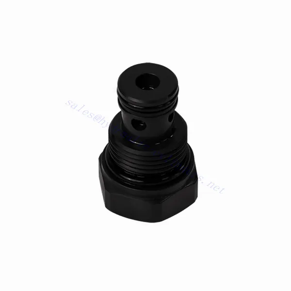
RVM-sarjan hydraulinen tarkistusventtiilipatruuna

RVM-sarjan hydraulinen takaiskuventtiili on luotettava ja monipuolinen komponentti hydraulisten järjestelmien optimaaliseen nesteensäätöön. Tämä venttiili on suunniteltu varmistamaan hydraulivirtauksen tehokas ja tarkka säätö, ja se tarjoaa poikkeuksellisen suorituskyvyn, kestävyyden ja helppokäyttöisyyden.
RVM-sarjan takaiskuventtiilipatruuna on luotettava ja tehokas ratkaisu hydraulisten järjestelmien nesteensäätöön. Tehokkaan takaiskuventtiilin toiminnallisuuden, kestävän rakenteen, kompaktin muotoilun ja suuren virtauskapasiteetin ansiosta tämä venttiilipatruuna varmistaa optimaalisen suorituskyvyn ja minimoi järjestelmävaurioiden riskin. Noudattamalla suositeltuja käyttö- ja huoltokäytäntöjä RVM-sarjan takaiskuventtiilipatruuna tarjoaa luotettavan toiminnan ja pidentää hydraulisten järjestelmien käyttöikää. Päivitä hydraulijärjestelmäsi RVM-sarjan takaiskuventtiilipatruunalla ja koe parannettu nesteensäätötehokkuus.
RVM-sarjan hydraulisen tarkastusventtiilin patruunan tärkeimmät ominaisuudet:
- Tehokas takaiskuventtiilin toiminnallisuus:
- RVM-sarjan venttiilipatruunassa on erittäin tehokas takaiskuventtiilimekanismi, joka mahdollistaa hydraulinesteen yksisuuntaisen virtauksen.
- Se estää tehokkaasti takaisinvirtauksen varmistaen sujuvan toiminnan ja minimoiden hydraulijärjestelmän vaurioitumisriskin.
- Vankka rakenne:
- Korkealaatuisista materiaaleista valmistettu RVM-sarjan venttiilipatruuna on poikkeuksellisen kestävä ja kulutusta kestävä, mikä takaa pitkän käyttöiän.
- Sen kestävä rakenne mahdollistaa sen kestävyyden korkeapaineisissa ympäristöissä ja vaativissa käyttöolosuhteissa.
- Kompakti ja monipuolinen muotoilu:
- Venttiilikasetti on kompakti, joten se sopii sovelluksiin, joissa on rajoitetusti tilaa tai painoa.
- Sen monipuolinen rakenne mahdollistaa helpon integroinnin erilaisiin hydraulijärjestelmiin, kuten teollisuuskoneisiin, liikkuviin laitteisiin ja voimanlähteisiin.
- Suuri virtauskapasiteetti:
- Kompaktista koostaan huolimatta RVM-sarjan venttiilipatruuna tarjoaa suuren virtauskapasiteetin, mikä mahdollistaa tehokkaan nesteensiirron ja optimaalisen järjestelmän suorituskyvyn.
- Se minimoi painehäviöt ja tuottaa toimilaitteille ja muille komponenteille maksimaalisen hydraulitehon.
RVM-sarjan tarkistushydraulisen venttiilipatruunan parametri:
| Paino | kg | 0.12 |
| Maks. käyttöpaine | baari | 350 |
| Halkeaman paine | baari | 0.2 0.5 |
| Maks. virtausnopeus | L/min | 30 |
| Viskositeettialue | mm2/s | Suositus 30-80, lupa 20-380 |
| Nesteen lämpötila-alue | ℃ | -30 - +80 (NBR-tiiviste) |
| -20 - +80 (FKM-tiiviste) | ||
| Neste | Mineraaliöljy, joka sopii NBR- ja FKM-tiivisteille | |
| Fosfaattiesteri FKM-tiivisteelle | ||
| Saastumisaste | Suurin sallittu nesteen kontaminaatioaste: Luokka 9. NAS 1638 tai 20/18/15, ISO4406 | |
RVM-sarjan tarkistusventtiilipatruunan edut:
• Tiivistys ilman vuotoja
• Patruunarakenne öljylohkon asennusta varten
RVM-sarjan tarkistusventtiilin käyttötapa Tarkista hydraulinen venttiilipatruuna :
- Järjestelmäanalyysi:
- Ennen asennusta analysoi hydrauliikkajärjestelmä huolellisesti määrittääksesi erityisvaatimukset ja käyttöparametrit.
- Ota huomioon tekijät, kuten virtausnopeudet, painearvot ja RVM-sarjan venttiilipatruunoiden yhteensopivuus.
- Venttiilin valinta:
- Valitse sopiva RVM-sarjan venttiilipatruunavaihtoehto järjestelmävaatimusten ja spesifikaatioiden perusteella.
- Ota huomioon tekijät, kuten virtauskapasiteetti, painearvot ja yhteensopivuus muiden järjestelmäkomponenttien kanssa.
- Asennus:
- Follow the manufacturer’s instructions for properly installing the RVM series valve cartridge in the hydraulic system.
- Varmista, että venttiili on tukevasti paikallaan, että se on oikein linjattu nesteen virtausreitin kanssa ja että tiivistys on riittävä vuotojen estämiseksi.
- Nesteen virtaussuunta:
- Varmista, että RVM-sarjan venttiilipatruuna on asennettu oikeaan suuntaan, jotta nesteen virtaussuunta on haluttu.
- Align the valve cartridge with the system’s flow path, ensuring proper engagement of the check valve mechanism.
Miten hydraulinen virtauksen säätöventtiili toimii?
A hydraulic flow control valve is a device used to regulate and control the speed of hydraulic fluid within a hydraulic system. It allows the operator to adjust the flow rate of the liquid, thereby preventing the speed of hydraulic actuators or controlling the rate of energy transfer. Here’s an explanation of how a hydraulic flow control valve works:
- Venttiilin rakenne:
- Hydraulinen virtauksen säätöventtiili koostuu tyypillisesti venttiilirungosta, jossa on tulo- ja poistoaukot, liikkuvasta kelasta tai lautasventtiilistä ja käyttömekanismista.
- Venttiilirunko sisältää sisäisiä kanavia ja kammioita, jotka säätelevät hydraulinesteen virtausta.
- Nesteen virtausreitit:
- Virtauksen säätöventtiilissä on tuloaukko, joka on kytketty hydrauliseen virtalähteeseen, kuten pumppuun, ja lähtöaukko, joka on kytketty hydrauliseen toimilaitteeseen tai muuhun komponenttiin.
- Venttiili tarjoaa nesteelle erilaisia virtausreittejä, mikä mahdollistaa sen ohjaamisen ja säätämisen.
- Kela tai lautanen:
- Venttiilirungossa on liikkuva kela tai lautasventtiili, joka säätelee hydraulinesteen virtausta.
- Kela voi liukua venttiilirungon sisällä, kun taas lautasventtiili voi liikkua lineaarisesti tai pyöriä avatakseen tai sulkeakseen tiettyjä kanavia.
- Käyttömekanismi:
- Hydraulisia virtauksen säätöventtiilejä voidaan käyttää manuaalisesti, sähköisesti tai muilla tavoin riippuen erityisistä suunnittelu- ja sovellusvaatimuksista.
- Manuaalinen käyttö tarkoittaa kahvan, nupin tai vivun säätämistä kelan tai poppetin asettamiseksi.
- Sähköisessä toiminnassa käytetään solenoideja, jotka vastaanottavat sähköisiä signaaleja kelan tai venttiilin siirtämiseksi, mikä mahdollistaa kauko-ohjauksen ja automatisoinnin.
- Venttiilien asennot:
- Hydraulisella virtauksen säätöventtiilillä on tyypillisesti useita asentoja, jotka kela tai lautasventtiili voi ottaa, ja joista jokainen vastaa tiettyä virtausnopeutta.
- Venttiilissä voi olla useita esiasetettuja asentoja tai se voi tarjota jatkuvaa säätöä virtausnopeuden hienosäätöä varten.
- Kun kela tai lautasventtiili siirtyy, se kohdistuu tiettyihin kanaviin avaamalla tai sulkemalla niitä nesteen virtauksen hallitsemiseksi.
- Virtauksen säätö:
- Säätämällä kelan tai lautasventtiilin asentoa käyttäjä voi säätää virtauskanavien kokoa ja siten hydraulinesteen virtausnopeutta.
- Kun kanavat ovat täysin auki, neste virtaa vapaasti, mikä mahdollistaa maksimaalisen virtausnopeuden.
- Kanavien osittainen sulkeminen rajoittaa virtausta, mikä vähentää virtausnopeutta ja säätelee hydraulisten toimilaitteiden nopeutta.
- Paineen kompensointi:
- Joissakin hydraulisissa virtauksen säätöventtiileissä on paineenkompensointimekanismeja, jotka ylläpitävät tasaista virtausnopeutta järjestelmän paineen muutoksista huolimatta.
- Nämä mekanismit varmistavat, että haluttu virtausnopeus säilyy, vaikka järjestelmässä olisi vaihteluita kuormituksessa tai paineessa.
Tehtaan kapasiteetti ja kapasiteetti:
(1) Kokoonpano
Meillä on ensiluokkainen riippumaton tutkimus- ja kehitystyön kokoonpanoalusta. Hydraulisylinterien tuotantopajassa on neljä puoliautomaattista nostosylinterin kokoonpanolinjaa ja yksi automaattinen kallistussylinterin kokoonpanolinja, joiden suunniteltu vuotuinen tuotantokapasiteetti on 1 miljoona kappaletta. Erikoissylinterin työpaja on varustettu erilaisilla eritelmillä puoliautomaattisen puhdistusasennuksen kokoonpanojärjestelmällä, jonka suunniteltu vuotuinen tuotantokapasiteetti on 200 000, ja se on varustettu kuuluisilla CNC-työstölaitteilla, työstökeskuksella, korkean tarkkuuden sylinterin käsittelyyn tarkoitetuilla erityislaitteilla, robottihitsauskoneella, automaattisella puhdistuslaitteella, automaattisella sylinterin kokoonpanokoneella ja automaattisella maalaustuotantolinjalla. Olemassa olevat kriittiset laitteet yli 300 sarjaa (sarjaa). Laiteresurssien optimaalinen kohdentaminen ja tehokas käyttö varmistavat tuotteiden tarkkuusvaatimukset ja täyttävät tuotteiden laatuvaatimukset.


(2) Koneistus
Työstöpaja on varustettu räätälöidyllä kaltevalla kiskosorvauskeskuksella, työstökeskuksella, suurnopeus-hiontakoneella, hitsausrobotilla ja muilla vastaavilla laitteilla, joilla voidaan käsitellä sylinteriputkia, joiden sisähalkaisija on enintään 400 mm ja enimmäispituus on 6 metriä.


(3) Hitsaus


(4) Maalaus ja pinnoitus
Pienillä ja keskisuurilla sylinterin automaattisilla vesipohjaisilla maalipinnoituslinjoilla automaattisen robotin lastaus- ja purku- ja automaattisen ruiskutuksen saavuttamiseksi, suunnittelukapasiteetti on 4000 kappaletta vuorossa;
Meillä on myös puoliautomaattinen maalauslinja suurille sylintereille, joka toimii voimaketjulla ja jonka suunnittelukapasiteetti on 60 laatikkoa työvuorossa.


(5) Testaus
Meillä on ensiluokkaiset tarkastustilat ja testialustat, joilla varmistetaan, että sylinterin suorituskyky täyttää vaatimukset.


Olemme yksi parhaista hydraulisylintereiden valmistajista. Voimme tarjota kattavia hydraulisylintereitä. Tarjoamme myös vastaavia maatalousvaihteistotOlemme vieneet tuotteitamme asiakkaille maailmanlaajuisesti ja ansainneet hyvän maineen erinomaisen tuotelaadun ja huoltopalvelumme ansiosta. Toivotamme tervetulleeksi asiakkaat kotimaassa ja ulkomailla ottamaan meihin yhteyttä neuvotellakseen liiketoimista, vaihtaakseen tietoja ja tehdä yhteistyötä kanssamme!