


Z2FRM-sarjan virtauksen säätöhydraulinen venttiili
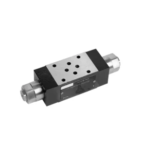

The Z2FRM series flow control hydraulic valve is a state-of-the-art hydraulic component designed to revolutionize the control and efficiency of hydraulic systems. With its advanced features and exceptional performance, this valve provides precise flow control and enhances the overall productivity of hydraulic machinery.
The Z2FRM series flow control hydraulic valve is a game-changing solution for precise flow control in hydraulic systems. With its unmatched precision, versatility, and durability, this valve empowers operators to optimize the performance and efficiency of their hydraulic machinery. By following the recommended usage methods and maintenance guidelines, you can unlock the full potential of the Z2FRM series flow control hydraulic valve, ensuring seamless operation and reliable flow control in your hydraulic applications. Upgrade your hydraulic system today and experience the power of precise hydraulic control with the Z2FRM series valve.
Z2FRM Series Flow Control Hydraulic Valve Key Characteristics:
- Precision Flow Control:
- The Z2FRM series valve offers unparalleled precision in controlling the flow rate of hydraulic fluids, allowing for fine-tuned adjustments and optimized performance.
- With its high accuracy, this valve ensures consistent flow control, resulting in enhanced system efficiency and improved productivity.
- Monipuoliset sovellukset:
- The Z2FRM series valve is highly versatile and compatible with a wide range of hydraulic systems, including industrial machinery, construction equipment, and mobile applications.
- Its adaptability makes it an ideal choice for diverse hydraulic setups, providing reliable and efficient flow control.
- Pressure and Temperature Stability:
- Engineered to withstand varying pressure and temperature conditions, the Z2FRM series valve maintains stable flow control even in demanding operational environments.
- It ensures consistent performance, minimizes flow fluctuations, and safeguards the integrity of the hydraulic system.
- Vankka rakenne:
- The Z2FRM Series Valve boasts a robust design and is crafted from high-quality materials, guaranteeing durability and long-lasting reliability.
- Its sturdy construction enables it to withstand high pressures, vibrations, and extreme temperatures, making it a dependable solution for critical hydraulic applications.
Z2FRM Series Flow Control Hydraulic Valve Parameter:
NG6
| Flow control valve | |||||||||||
| Max. operating pressure-Port A | baari | 315 | |||||||||
| Pressure differential ΔP for free return flow B to A | See characteristic curves | ||||||||||
| Minimum pressure differential | baari | 6 to 14 | |||||||||
| Pressure stability up to P= 315 bar | % | ±2(Qmax) | |||||||||
| Flow | Qmax | L/min | 0.2 | 0.6 | 1.5 | 3 | 6 | 10 | 16 | 25 | 32 |
| Qmin to 100bar | mL/min | 15 | 15 | 15 | 15 | 25 | 50 | 70 | 100 | 250 | |
| Qmin to 315bar | 25 | 25 | 25 | 25 | 25 | 50 | 70 | 100 | 250 | ||
| Neste | Mineral oil, Phosphate ester | ||||||||||
| Nesteen lämpötila-alue | ℃ | – 20 to + 80 | |||||||||
| Viskositeettialue | mm2/s | 10 to 800 | |||||||||
| Saastumisaste | Suurin sallittu nesteen kontaminaatioaste: Luokka 9. NAS 1638 tai 20/18/15, ISO4406 | ||||||||||
| Asennusasento | Valinnainen | ||||||||||
| Olosuhteet lämpötila-alue | ℃ | -20 to +50 | |||||||||
| Paino | 2FRM6A…2FRM6B… | kg | about 1.3 | ||||||||
| 2FRM6SB… | kg | about 1.5 | |||||||||
| Rectifiere | |||||||||||
| Nominal flow | baari | 320 | |||||||||
| Maks. käyttöpaine | baari | to 210 | |||||||||
| Halkeaman paine | baari | 0.7 | |||||||||
| Paino | kg | about 0.9 | |||||||||
NG5/10/16
| Flow control valve | ||||||||||||||||
| Max. operating pressure-Port A | baari | 315 | ||||||||||||||
| Pressure differential ΔP for free return flow B to A | See characteristic curves | |||||||||||||||
| Minimum pressure differential | baari | 6 to 14 | ||||||||||||||
| Neste | Mineral oil, Phosphate ester | |||||||||||||||
| Nesteen lämpötila-alue | ℃ | – 20 to + 80 | ||||||||||||||
| Viskositeettialue | mm2/s | 10 to 800 | ||||||||||||||
| Saastumisaste | Suurin sallittu nesteen kontaminaatioaste: Luokka 9. NAS 1638 tai 20/18/15, ISO4406 | |||||||||||||||
| Koko | mm | 5 | 10 | 16 | ||||||||||||
| Maks. virtausnopeus | L/min | 0.2 | 0.6 | 1.2 | 3 | 6 | 10 | 15 | 10 | 16 | 25 | 50 | 60 | 100 | 160 | |
| Oil return flow B to A | mL/min | 0.5 | 0.5 | 0.6 | 0.9 | 1.8 | 3.6 | 6.7 | 2 | 2.5 | 3.5 | 6 | 2.8 | 4.3 | 7.3 | |
| flow stable range (%Qmax)(-20-±80℃) | ±5 | ±3 | ±2 | ±2 | ||||||||||||
| ±2 (P=210 bar) | ±2 (P=350 bar) | |||||||||||||||
| Working pressure | baari | 210 | 350 | |||||||||||||
| Min.pressure drawdown | baari | 3-5 | 6-8 | 3-7 | 5-12 | |||||||||||
| Paino | kg | 1.6 | 3.4 | 7.4 | ||||||||||||
| Rectifiere | ||||||||||||||||
| Neste | Mineral oil, Phosphate ester | |||||||||||||||
| Nesteen lämpötila-alue | -20 to +80 | |||||||||||||||
| Viskositeettialue | 10–800 | |||||||||||||||
| Saastumisaste | Suurin sallittu nesteen kontaminaatioaste: Luokka 9. NAS 1638 tai 20/18/15, ISO4406 | |||||||||||||||
| Koko | 5 | 10 | 16 | |||||||||||||
| Flow | 15 | 50 | 160 | |||||||||||||
| Working pressure | 210 | 315 | 315 | |||||||||||||
| Halkeaman paine | 1 | 1.5 | 1.5 | |||||||||||||
| Paino | 0.6 | 3.2 | 9.3 | |||||||||||||
Z2FRM Series Flow Control Hydraulic Valve Advantages:
• Base sub-plate mounting see product catalog
• Pressure compensation displacement restrictor, optional
• Valinnainen yksisuuntainen venttiili
• Knob with scale, optional lockability
Usage Method Of Z2FRM Series Flow Control Hydraulic Valve:
- Järjestelmän arviointi:
- Begin by assessing the specific requirements of your hydraulic system, including desired flow rates, pressure ranges, and flow control parameters.
- Determine if the Z2FRM series valve suits your application based on its flow control capabilities and compatibility with your system.
- Venttiilin valinta:
- Select the appropriate variant of the Z2FRM series valve based on your system parameters, desired flow rate, and compatibility with other system components.
- Consider factors such as maximum flow capacity, pressure rating, and operational conditions.
- Asennus:
- Follow the manufacturer’s installation instructions meticulously, ensuring precise alignment and secure valve connections.
- Pay close attention to the flow direction indicators, ensuring the correct positioning of the valve within the hydraulic system.
- Flow Control Adjustment:
- Once installed, adjust the flow control settings of the valve to achieve the desired flow rate and meet your system requirements.
- Fine-tune the valve to optimize the speed and performance of hydraulic actuators, thereby maximizing overall system efficiency.
How To Add A Hydraulic Valve To A Tractor?
Adding a hydraulic valve to a tractor can expand its functionality and enable the use of hydraulic attachments and implements. Here are the general steps to follow when adding a hydraulic valve to a tractor:
- Determine the Tractor’s Hydraulic System:
- Check if your tractor already has a hydraulic system in place. Many modern tractors come equipped with hydraulic systems, while older models may require modifications or additional components.
- Choose the Right Hydraulic Valve:
- Select a hydraulic valve that suits your specific needs and requirements. Consider factors such as flow rate, pressure rating, number of spools, and compatibility with your tractor’s hydraulic system.
- Kerää tarvittavat työkalut ja materiaalit:
- Ensure you have all the required tools and materials for the installation process. This may include wrenches, hydraulic hoses, fittings, mounting brackets, and the hydraulic valve itself.
- Identify the Installation Location:
- Determine the ideal location for mounting the hydraulic valve on your tractor. This is typically near the existing hydraulic ports or in a convenient and accessible position.
- Prepare the Tractor:
- Before installation, shut off the tractor’s engine and relieve any pressure in the hydraulic system by moving the hydraulic control levers back and forth.
- Install the Hydraulic Valve:
- Mount the hydraulic valve securely using the appropriate brackets or mounting hardware. Ensure it is positioned correctly and aligned with the hydraulic ports.
- Connect the Hydraulic Hoses:
- Attach hydraulic hoses to the valve’s ports, ensuring a secure connection. Use appropriate fittings and tighten them properly to prevent leaks.
- Connect to the Tractor’s Hydraulic System:
- Identify the tractor’s existing hydraulic ports or couplers. Connect the hydraulic hoses from the valve to these ports, matching the appropriate fittings.
- Test for Leaks:
- Once all connections are made, start the tractor’s engine and operate the hydraulic controls. Carefully inspect all connections for any signs of hydraulic fluid leaks. Address any leaks promptly by tightening fittings or replacing damaged components.
- Test the Hydraulic Valve:
- Engage the hydraulic controls and test the operation of the newly installed hydraulic valve. Ensure that it functions smoothly and controls the hydraulic attachments as intended.
- Secure and Protect the Hoses:
- Secure the hydraulic hoses in place using clamps or brackets to prevent them from interfering with other tractor components or getting damaged during operation. Consider using protective covers for the hoses to safeguard them from environmental elements and potential abrasion.
Tehtaan kapasiteetti ja kapasiteetti:
(1) Kokoonpano
Meillä on ensiluokkainen riippumaton tutkimus- ja kehitystyön kokoonpanoalusta. Hydraulisylinterien tuotantopajassa on neljä puoliautomaattista nostosylinterin kokoonpanolinjaa ja yksi automaattinen kallistussylinterin kokoonpanolinja, joiden suunniteltu vuotuinen tuotantokapasiteetti on 1 miljoona kappaletta. Erikoissylinterin työpaja on varustettu erilaisilla eritelmillä puoliautomaattisen puhdistusasennuksen kokoonpanojärjestelmällä, jonka suunniteltu vuotuinen tuotantokapasiteetti on 200 000, ja se on varustettu kuuluisilla CNC-työstölaitteilla, työstökeskuksella, korkean tarkkuuden sylinterin käsittelyyn tarkoitetuilla erityislaitteilla, robottihitsauskoneella, automaattisella puhdistuslaitteella, automaattisella sylinterin kokoonpanokoneella ja automaattisella maalaustuotantolinjalla. Olemassa olevat kriittiset laitteet yli 300 sarjaa (sarjaa). Laiteresurssien optimaalinen kohdentaminen ja tehokas käyttö varmistavat tuotteiden tarkkuusvaatimukset ja täyttävät tuotteiden laatuvaatimukset.


(2) Koneistus
Työstöpaja on varustettu räätälöidyllä kaltevalla kiskosorvauskeskuksella, työstökeskuksella, suurnopeus-hiontakoneella, hitsausrobotilla ja muilla vastaavilla laitteilla, joilla voidaan käsitellä sylinteriputkia, joiden sisähalkaisija on enintään 400 mm ja enimmäispituus on 6 metriä.


(3) Hitsaus


(4) Maalaus ja pinnoitus
Pienillä ja keskisuurilla sylinterin automaattisilla vesipohjaisilla maalipinnoituslinjoilla automaattisen robotin lastaus- ja purku- ja automaattisen ruiskutuksen saavuttamiseksi, suunnittelukapasiteetti on 4000 kappaletta vuorossa;
Meillä on myös puoliautomaattinen maalauslinja suurille sylintereille, joka toimii voimaketjulla ja jonka suunnittelukapasiteetti on 60 laatikkoa työvuorossa.


(5) Testaus
Meillä on ensiluokkaiset tarkastustilat ja testialustat, joilla varmistetaan, että sylinterin suorituskyky täyttää vaatimukset.


Olemme yksi parhaista hydraulisylintereiden valmistajista. Voimme tarjota kattavia hydraulisylintereitä. Tarjoamme myös vastaavia maatalousvaihteistotOlemme vieneet tuotteitamme asiakkaille maailmanlaajuisesti ja ansainneet hyvän maineen erinomaisen tuotelaadun ja huoltopalvelumme ansiosta. Toivotamme tervetulleeksi asiakkaat kotimaassa ja ulkomailla ottamaan meihin yhteyttä neuvotellakseen liiketoimista, vaihtaakseen tietoja ja tehdä yhteistyötä kanssamme!