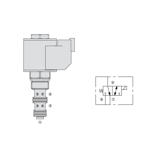
30SD08-30 Solenoid Directional Valve
Yhtenä hydraulisylinterien valmistajista, toimittajista ja mekaanisten tuotteiden viejistä tarjoamme hydraulisylintereitä ja monia muita tuotteita.
Ota yhteyttä meihin saadaksesi lisätietoja.
Posti:sales@hydraulic-cylinders.net
Valmistaja toimittaja viejä hydraulisylinterit.
30SD08-30 Solenoid Directional Valve
Experience unparalleled precision and control in your hydraulic system with the 30SD08-30 solenoid directional valve. This high-performance valve is designed to meet the demands of industrial applications, offering seamless fluid flow management and reliable operation.
The 30SD08-30 solenoid directional valve is a game-changer for hydraulic systems, offering precise control, high flow capacity, and rapid response time. With its durability and reliability, this valve guarantees optimal performance and efficiency. By following the recommended usage methods and maintenance guidelines, you can harness the full potential of the 30SD08-30 solenoid directional valve, achieving seamless control, increased productivity, and improved overall performance. Upgrade your hydraulic system today with the 30SD08-30 solenoid directional valve and experience the precision and reliability it brings to your operations.
30SD08-26 Solenoid Directional Valve Characteristics:
- Accurate Fluid Flow Control:
- The 30SD08-30 solenoid directional valve provides precise control over fluid flow, ensuring accurate and reliable operation of your hydraulic system.
- Experience seamless adjustments in flow rates, facilitating optimal performance in various industrial applications.
- Suuri virtauskapasiteetti:
- With its high flow capacity design, the 30SD08-30 solenoid directional valve can handle substantial fluid volumes efficiently.
- This feature enables smooth and reliable operation, even in applications that require high flow rates, ensuring optimal system performance.
- Nopea vasteaika:
- Equipped with advanced solenoid technology, the 30SD08-30 solenoid directional valve boasts a rapid response time.
- Experience swift and accurate adjustments in fluid flow direction, allowing for enhanced system efficiency and precise control.
- Kestävyys ja luotettavuus:
- Built to withstand demanding operating conditions, the 30SD08-30 solenoid directional valve features a robust construction.
- Its durable materials and reliable design minimize downtime, reduce maintenance requirements, and ensure long-lasting performance.
30SD08-25 Solenoid Directional Valve Parameter:
| Nimellispaine | 207 baaria (3000 psi) |
| Huippuvirtaus | Katso suorituskykykaavio |
| Neste | Mineraalipohjaiset tai synteettiset voiteluominaisuudet |
| Nesteen lämpötila-alue ℃ | -54 to 107 ℃ (Polyurethane seals) |
| -40 - 100 ℃ (Buna N -tiivisteet) | |
| -26 - 204 ℃ (fluorihiilitiivisteet) | |
| Viskositeettialue | 7,4–420 mm2/s |
| Saastumisaste | Minimipäästötaso on ISO4406-taso 20/18/14, ja käyttöiän pidentämiseksi suositellaan tasoa 17/15/13. |
| Sisäinen vuoto | Port 3 (De-energized): ≤ 82 mL/min@207bar |
| Port 1 (Energized): ≤ 164 mL/min@207bar | |
| Ontelo | VC08-3(Cavity variation ‘A’, see technical reference) |
| Käämin käyttöikä | Jatkuva nimellisjännitteellä 85% - 115% |
| Alkuperäinen kelan virrankulutus 20 ℃:ssa | 1,4 A 12 VDC:n jännitteellä; 0,7 A 24 VDC:n jännitteellä |
| Minimivetojännite | 85% nimellispaineesta 207 barin (3000 psi) paineessa |
30SD08-25 Solenoid Directional Valve Advantages:
• Jatkuvatoiminen kela
• Tehokas märkärakenteinen rakenne
• Äänirasiat ovat jännitteeltään vaihdettavissa
• Lisävarusteena vedenpitävät E-kelat, joiden luokitus on jopa IP69K
• Karkaistut osat pitkän käyttöiän takaamiseksi
Usage Method Of 30SD08-25 Solenoid Directional Valve:
- Järjestelmän arviointi:
- Begin by assessing the specific requirements of your hydraulic system, considering flow rates, pressure levels, and system dynamics.
- Evaluate if the 30SD08-30 Solenoid Directional Valve aligns with your system’s needs, taking into account its precision, flow capacity, and compatibility with other components.
- Venttiilin valinta:
- Select the appropriate variant of the 30SD08-30 solenoid directional valve based on your system parameters and performance requirements.
- Consider factors such as flow capacity, pressure ratings, and compatibility to ensure seamless integration and optimal functionality.
- Asennus:
- Follow the manufacturer’s installation instructions carefully to ensure proper placement and secure mounting of the valve.
- Aseta venttiili oikein hydraulijärjestelmään ottaen huomioon nesteen virtaussuunnan ja huollon kannalta tarvittavan helppopääsyisyyden.
- Sähköliitännät:
- Kytke solenoidiventtiili valmistajan ohjeiden mukaisesti määrättyyn virtalähteeseen.
- Ensure that the electrical connections are secure, adhering to safety standards and guidelines.
Kuinka kytkeä hydraulinen virtauksen säätöventtiili?
Kytke hydraulinen virtauksen säätöventtiili seuraavasti:
- Tunnista venttiilityyppi: Määritä käyttämäsi virtauksen säätöventtiilin tyyppi. Yleisiä tyyppejä ovat neulaventtiilit, säädettävät virtauksen säätöventtiilit tai painekompensoidut virtauksen säätöventtiilit. Varmista, että venttiili sopii sovellukseesi ja on yhteensopiva hydrauliikkajärjestelmäsi kanssa.
- Kerää tarvittavat työkalut ja materiaalit: Kerää tarvittavat työkalut ja materiaalit, mukaan lukien sopivat hydrauliliittimet, adapterit, letkut ja jakoavaimet.
- Valmistele hydrauliikkajärjestelmä: Sammuta hydraulijärjestelmä ja vapauta järjestelmästä mahdollinen paine aktivoimalla paineenalennusventtiili tai vetämällä hydraulisylinterit sisään. Tämä vaihe on ratkaisevan tärkeä turvallisuuden kannalta.
- Virtaussuunnan tunnistaminen: Tunnista hydrauliikkajärjestelmän virtaussuunta. Virtaussuunta on yleensä merkitty hydrauliikkakomponenttien nuolilla. Varmista, että ymmärrät oikean virtaussuunnan ennen kuin jatkat.
- Paikanna asennuspiste: Määritä virtauksen säätöventtiilin optimaalinen asennuspaikka hydraulijärjestelmässäsi. Ota huomioon tekijät, kuten saavutettavuus, toimilaitteen tai hydraulikomponentin läheisyys ja säädön helppous.
- Asenna venttiili: Kiinnitä virtauksen säätöventtiili tukevasti valittuun paikkaan käyttämällä sopivia kiinnikkeitä tai puristimia. Varmista, että venttiili on oikeassa asennossa ja että tulo- ja lähtöaukot ovat virtaussuunnan mukaiset.
- Yhdistä tulo- ja lähtöportit: Kiinnitä hydrauliletkut tai -putket virtauksen säätöventtiilin tulo- ja lähtöportteihin. Käytä sopivia hydrauliliittimiä ja sovittimia vuotamattoman liitoksen luomiseksi. Kiristä liitokset avaimilla varmistaaksesi tukevan kiinnityksen, mutta vältä liiallista kiristämistä.
- Säädä virtauksen säätöä: Virtauksen säätöventtiilin tyypistä riippuen siinä voi olla säädettäviä ominaisuuksia, kuten neulaventtiili tai virtauksen säätönuppi. Säädä venttiili halutun virtausnopeuden tai -nopeuden mukaan. Katso valmistajan ohjeet tarkemmista säätötoimenpiteistä.
- Testaa järjestelmä: Kun virtauksen säätöventtiili on asennettu ja säädetty, palauta hydraulijärjestelmän paine hitaasti. Testaa järjestelmä varmistaaksesi, että virtauksen säätöventtiili toimii oikein. Tarkkaile hydraulisen toimilaitteen virtausnopeutta tai nopeutta varmistaaksesi, että se on halutulla alueella.
- Hienosäätö ja seuranta: Säädä virtauksen säätöventtiiliä halutun virtausnopeuden tai -nopeuden saavuttamiseksi. Tarkkaile hydraulijärjestelmää säännöllisesti vuotojen, paineen epätasaisuuksien tai epätavallisen käyttäytymisen varalta.
Tehtaan kapasiteetti ja kapasiteetti:
(1) Kokoonpano
Meillä on ensiluokkainen riippumaton tutkimus- ja kehitystyön kokoonpanoalusta. Hydraulisylinterien tuotantopajassa on neljä puoliautomaattista nostosylinterin kokoonpanolinjaa ja yksi automaattinen kallistussylinterin kokoonpanolinja, joiden suunniteltu vuotuinen tuotantokapasiteetti on 1 miljoona kappaletta. Erikoissylinterin työpaja on varustettu erilaisilla eritelmillä puoliautomaattisen puhdistusasennuksen kokoonpanojärjestelmällä, jonka suunniteltu vuotuinen tuotantokapasiteetti on 200 000, ja se on varustettu kuuluisilla CNC-työstölaitteilla, työstökeskuksella, korkean tarkkuuden sylinterin käsittelyyn tarkoitetuilla erityislaitteilla, robottihitsauskoneella, automaattisella puhdistuslaitteella, automaattisella sylinterin kokoonpanokoneella ja automaattisella maalaustuotantolinjalla. Olemassa olevat kriittiset laitteet yli 300 sarjaa (sarjaa). Laiteresurssien optimaalinen kohdentaminen ja tehokas käyttö varmistavat tuotteiden tarkkuusvaatimukset ja täyttävät tuotteiden laatuvaatimukset.


(2) Koneistus
Työstöpaja on varustettu räätälöidyllä kaltevalla kiskosorvauskeskuksella, työstökeskuksella, suurnopeus-hiontakoneella, hitsausrobotilla ja muilla vastaavilla laitteilla, joilla voidaan käsitellä sylinteriputkia, joiden sisähalkaisija on enintään 400 mm ja enimmäispituus on 6 metriä.

(3) Hitsaus

(4) Maalaus ja pinnoitus
Pienillä ja keskisuurilla sylinterin automaattisilla vesipohjaisilla maalipinnoituslinjoilla automaattisen robotin lastaus- ja purku- ja automaattisen ruiskutuksen saavuttamiseksi, suunnittelukapasiteetti on 4000 kappaletta vuorossa;
Meillä on myös puoliautomaattinen maalauslinja suurille sylintereille, joka toimii voimaketjulla ja jonka suunnittelukapasiteetti on 60 laatikkoa työvuorossa.


(5) Testaus
Meillä on ensiluokkaiset tarkastustilat ja testialustat, joilla varmistetaan, että sylinterin suorituskyky täyttää vaatimukset.

Olemme yksi parhaista hydraulisylintereiden valmistajista. Voimme tarjota kattavia hydraulisylintereitä. Tarjoamme myös vastaavia maatalousvaihteistotOlemme vieneet tuotteitamme asiakkaille maailmanlaajuisesti ja ansainneet hyvän maineen erinomaisen tuotelaadun ja huoltopalvelumme ansiosta. Toivotamme tervetulleeksi asiakkaat kotimaassa ja ulkomailla ottamaan meihin yhteyttä neuvotellakseen liiketoimista, vaihtaakseen tietoja ja tehdä yhteistyötä kanssamme!
Hydraulisylinteri Sovellus:
