

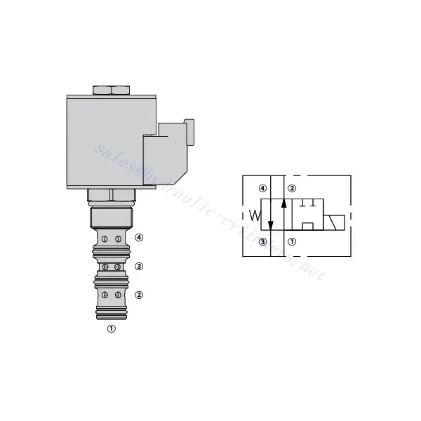
30SD10-44 Solenoid Directional Valve

The 30SD10-44 solenoid directional valve is a high-performance hydraulic component designed to provide exceptional efficiency and precise control in a wide range of applications. With advanced engineering and cutting-edge technology, this valve allows for seamless directional control of hydraulic fluid, enabling reliable operation in various industries. From industrial machinery to mobile equipment, the 30SD10-44 solenoid directional valve is the trusted solution for optimizing hydraulic systems.
The 30SD10-44 solenoid directional valve offers exceptional efficiency, control, and durability for hydraulic systems. Its precise directional control capabilities, robust construction, and easy installation make it an excellent choice for various applications. By following the recommended maintenance practices, you can ensure optimal performance and extend the lifespan of this valve. Invest in the 30SD10-44 solenoid directional valve today and experience enhanced efficiency and control in your hydraulic systems.
30SD10-44 Solenoid Directional Valve Characteristics:
- Robust Construction: The 30SD10-44 solenoid directional valve is built to withstand demanding environments. Constructed from high-quality materials, it offers exceptional durability and longevity, ensuring reliable performance even in harsh conditions.
- High Flow Capacity: This valve boasts a high flow capacity, enabling efficient and rapid movement of hydraulic fluid. It facilitates quick response times and enhances the overall productivity of hydraulic systems.
- Easy Installation: The 30SD10-44 solenoid directional valve is designed for hassle-free installation. It features standardized connections and mounting options, making integrating your hydraulic system a breeze.
- Versatile Applications: This valve is suitable for various applications across various industries. Whether in manufacturing, construction, or agriculture, the 30SD10-44 solenoid directional valve can be customized to meet your specific hydraulic control needs.
30SD10-44 Solenoid Directional Valve Parameter:
| Nimellispaine | 207 bar (3000 psi) | |
| Huippuvirtaus | 23 L/min (6 gpm) | |
| Neste | Mineraalipohjaiset tai synteettiset voiteluominaisuudet | |
| Nesteen lämpötila-alue ℃ | -54 - 107 ℃ (polyuretaanitiivisteet) | |
| -40 - 100 ℃ (Buna N -tiivisteet) | ||
| -26 - 204 ℃ (fluorihiilitiivisteet) | ||
| Viskositeettialue | 7,4–420 mm2/s | |
| Saastumisaste | Minimipäästötaso on ISO4406-taso 20/18/14, ja käyttöiän pidentämiseksi suositellaan tasoa 17/15/13. | |
| Sisäinen vuoto | ≤ 82 mL/min@207 bar | |
| Ontelo | VC10-4 | |
| Käämin käyttöikä | Jatkuva nimellisjännitteellä 85% - 115% | |
| Alkuperäinen kelan virrankulutus 20 ℃:ssa | Sähkökela | 1,7 A 12 VDC:n jännitteellä; 0,85 A 24 VDC:n jännitteellä |
| D-kela | 1,67 A 12 VDC:n jännitteellä; 0,83 A 24 VDC:n jännitteellä | |
| Minimivetojännite | 85% nimellispaineesta 207 barissa | |
30SD10-44 Solenoid Directional Valve Advantages:
• Jatkuvatoiminen kela
• Äänirasiat ovat jännitteeltään vaihdettavissa
• Lisävarusteena vedenpitävät E-kelat, joiden luokitus on jopa IP69K
• Tehokas märkärakenteinen rakenne
• Teollisuuden yhteinen ontelo
• Karkaistut osat pitkän käyttöiän takaamiseksi
Usage Method Of 30SD10-44 Solenoid Directional Valve:
Using the 30SD10-44 solenoid directional valve is straightforward and user-friendly. Here’s a step-by-step guide to get you started:
- Prepare the System: Ensure the hydraulic system is appropriately set up and all necessary components are in place.
- Mount the Valve: Install the 30SD10-44 solenoid directional valve in the desired location within the hydraulic system and secure it tightly using appropriate mounting brackets or fasteners.
- Connect the Plumbing: Connect the hydraulic lines to the valve’s designated ports. Ensure proper alignment and tighten the connections to prevent leaks.
- Electrical Connections: Connect the solenoid valve to the electrical power supply. Follow the wiring diagram provided with the valve to connect the wires and ensure safe operation correctly.
- Test and Adjust: Once the valve is installed and connected, test its functionality by activating the solenoid and observing the directional control of the hydraulic fluid. Make any necessary adjustments to ensure proper operation.
How To Install A Moen Shower Valve Cartridge?
Installing a Moen shower valve cartridge requires careful attention to detail to ensure proper functioning of your shower system. Here’s a step-by-step guide to help you with the installation process:
- Gather the Required Tools: Before starting, gather the necessary tools, including an adjustable wrench, pliers, screwdriver, and a cartridge puller (if needed).
- Turn Off the Water Supply: Locate the main water shut-off valve for your house and turn it off to stop the water flow to the shower. If you have a dedicated shut-off valve for the shower, you can use that instead.
- Remove the Handle and Trim: Remove the handle by locating the set screw or screw cover on the handle and using a screwdriver or Allen wrench to loosen and remove it. Once the screw is removed, pull the handle off. Next, remove the trim plate or escutcheon surrounding the valve using a screwdriver.
- Take Out the Old Cartridge: Depending on the Moen shower valve model, the cartridge removal method may vary. Some cartridges can be pulled out by hand, while others may require a cartridge puller. If your cartridge is stubborn and won’t come out easily, refer to the manufacturer’s instructions or consult a professional for assistance.
- Prepare the New Cartridge: Before installing the new cartridge, make sure it matches the model and type specified by Moen for your shower valve. Follow any included instructions or guidelines provided with the cartridge.
- Install the New Cartridge: Insert the new cartridge into the valve body, aligning it properly. Push it firmly but gently until it is fully seated in the valve. Ensure that it is correctly aligned with any tabs or grooves in the valve body.
- Reassemble the Trim and Handle: Replace the trim plate or escutcheon over the valve and secure it with screws. Then, slide the handle back onto the valve stem and tighten the set screw or screw cover to secure it in place.
- Turn On the Water Supply: Once the cartridge and handle are securely in place, turn on the main water supply or dedicated shower shut-off valve to restore the water flow to the shower.
- Test the Functionality: Turn on the shower to test the new cartridge’s functionality. Check for any leaks, unusual noises, or issues with water flow and temperature. Make any necessary adjustments to ensure smooth operation.
Tehtaan kapasiteetti ja kapasiteetti:
(1) Kokoonpano
Meillä on ensiluokkainen riippumaton tutkimus- ja kehitystyön kokoonpanoalusta. Hydraulisylinterien tuotantopajassa on neljä puoliautomaattista nostosylinterin kokoonpanolinjaa ja yksi automaattinen kallistussylinterin kokoonpanolinja, joiden suunniteltu vuotuinen tuotantokapasiteetti on 1 miljoona kappaletta. Erikoissylinterin työpaja on varustettu erilaisilla eritelmillä puoliautomaattisen puhdistusasennuksen kokoonpanojärjestelmällä, jonka suunniteltu vuotuinen tuotantokapasiteetti on 200 000, ja se on varustettu kuuluisilla CNC-työstölaitteilla, työstökeskuksella, korkean tarkkuuden sylinterin käsittelyyn tarkoitetuilla erityislaitteilla, robottihitsauskoneella, automaattisella puhdistuslaitteella, automaattisella sylinterin kokoonpanokoneella ja automaattisella maalaustuotantolinjalla. Olemassa olevat kriittiset laitteet yli 300 sarjaa (sarjaa). Laiteresurssien optimaalinen kohdentaminen ja tehokas käyttö varmistavat tuotteiden tarkkuusvaatimukset ja täyttävät tuotteiden laatuvaatimukset.


(2) Koneistus
Työstöpaja on varustettu räätälöidyllä kaltevalla kiskosorvauskeskuksella, työstökeskuksella, suurnopeus-hiontakoneella, hitsausrobotilla ja muilla vastaavilla laitteilla, joilla voidaan käsitellä sylinteriputkia, joiden sisähalkaisija on enintään 400 mm ja enimmäispituus on 6 metriä.


(3) Hitsaus


(4) Maalaus ja pinnoitus
Pienillä ja keskisuurilla sylinterin automaattisilla vesipohjaisilla maalipinnoituslinjoilla automaattisen robotin lastaus- ja purku- ja automaattisen ruiskutuksen saavuttamiseksi, suunnittelukapasiteetti on 4000 kappaletta vuorossa;
Meillä on myös puoliautomaattinen maalauslinja suurille sylintereille, joka toimii voimaketjulla ja jonka suunnittelukapasiteetti on 60 laatikkoa työvuorossa.


(5) Testaus
Meillä on ensiluokkaiset tarkastustilat ja testialustat, joilla varmistetaan, että sylinterin suorituskyky täyttää vaatimukset.


Olemme yksi parhaista hydraulisylintereiden valmistajista. Voimme tarjota kattavia hydraulisylintereitä. Tarjoamme myös vastaavia maatalousvaihteistotOlemme vieneet tuotteitamme asiakkaille maailmanlaajuisesti ja ansainneet hyvän maineen erinomaisen tuotelaadun ja huoltopalvelumme ansiosta. Toivotamme tervetulleeksi asiakkaat kotimaassa ja ulkomailla ottamaan meihin yhteyttä neuvotellakseen liiketoimista, vaihtaakseen tietoja ja tehdä yhteistyötä kanssamme!