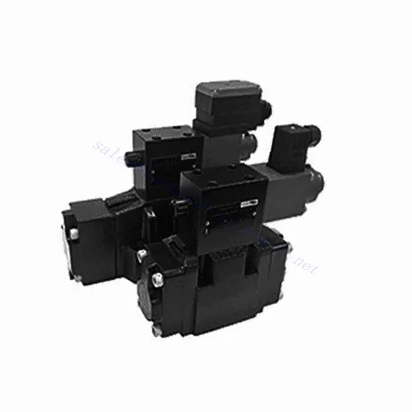
3DRE/M(E) Series 3-way Pilot Operated Proportional Pressure Reducing Hydraulic Valve
Yhtenä hydraulisylinterien valmistajista, toimittajista ja mekaanisten tuotteiden viejistä tarjoamme hydraulisylintereitä ja monia muita tuotteita.
Ota yhteyttä meihin saadaksesi lisätietoja.
Posti:sales@hydraulic-cylinders.net
Valmistaja toimittaja viejä hydraulisylinterit.
3DRE/M(E) Series 3-way Pilot Operated Proportional Pressure Reducing Hydraulic Valve
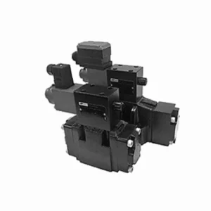
The 3DRE/M(E) series 3-way pilot-operated proportional pressure-reducing hydraulic valve is a cutting-edge hydraulic component designed to deliver accurate pressure control in hydraulic systems. With its advanced pilot-operated proportional control technology, this valve ensures precise regulation, efficient performance, and reliable operation.
The 3DRE/M(E) series 3-way proportional pressure-reducing hydraulic valve empowers hydraulic systems with precise pressure control, efficiency, and reliable performance. With its advanced proportional control technology and 3-way configuration, this valve offers versatility and flexibility in pressure regulation across different hydraulic circuits. By following the recommended usage methods and maintenance guidelines, you can maximize the benefits and longevity of the 3DRE/M(E) series valve, optimizing pressure control and overall performance in your hydraulic system. Upgrade your hydraulic setup today and experience superior pressure regulation with the 3DRE/M(E) series 3-way proportional pressure-reducing hydraulic valve.
3DRE/M(E) Series 3-way Pilot Operated Proportional Pressure Reducing Hydraulic Valve Key Characteristics:
- Proportional Pressure Control:
- The 3DRE/M(E) series valve offers precise and proportional pressure control, enabling dynamic adjustment of hydraulic pressure levels.
- This feature ensures accurate pressure regulation, maintaining a consistent and safe pressure within the hydraulic system.
- Pilottikäyttöinen suunnittelu:
- With its pilot-operated design, the valve delivers enhanced precision and responsiveness in pressure control.
- It utilizes a pilot valve to modulate the main valve, allowing for precise adjustments and improved control over pressure reduction.
- 3-way Configuration:
- The 3DRE/M(E) series valve features a versatile 3-way configuration, providing flexibility in controlling pressure across different hydraulic circuits.
- It allows for simultaneous pressure reduction in one circuit while supplying pressure to another course.
- Tehokas suorituskyky:
- By utilizing advanced proportional control technology, the valve ensures efficient performance, optimizing energy usage and reducing operational costs.
- It minimizes pressure fluctuations, enhancing system efficiency and contributing to overall productivity.
3DRE/M(E) Series 3-way Pilot Operated Proportional Pressure Reducing Hydraulic Valve Parameter:
| Hydraulinen | ||||||||
| Asennusasento | optional, preferably horizontal | |||||||
| Koko | 6 | 10 | ||||||
| Paino | 4WRA…L2X | Kg | 2 | 6.6 | ||||
| 4WRAE…L2X | 2.2 | 6.8 | ||||||
| Rated flow qnom,when Δp = 10 bar | L/min | 7、15、26 | 30、60 | |||||
| Hystereesi | % | ≤5 | ||||||
| Toistettavuus | % | ≤1 | ||||||
| Response sensitivity | % | ≤0.5 | ||||||
| Maks. käyttöpaine | Port s A B P | baari | 315 | |||||
| Portti T | baari | 210 | ||||||
| Neste | Mineraaliöljy, joka sopii NBR- ja FKM-tiivisteille | |||||||
| Fosfaattiesteri FKM-tiivisteelle | ||||||||
| Nesteen lämpötila-alue | 4WRA…L2X | ℃ | -20℃ to 70℃(-4°F to 158°F) | |||||
| 4WRAE…L2X | ℃ | -20℃ to 50℃(-4° F to 122° F) | ||||||
| Viskositeettialue | mm²/s | 20 to 380(preferably 30 to 46) | ||||||
| Saastumisaste | NAS1638 class9 or ISO 4406 class 20/18/15 | |||||||
| Sähkötiedot | ||||||||
| 1)solenoid | ||||||||
| Voltage type | DC | |||||||
| Command value signal | ±10V or 4~20mA | |||||||
| Max. current per solenoid | A | 2.5 | 1.5 | 0.8 | ||||
| Käämin vastus | Cold value | Ω | 2 | 4.8 | 19.5 | |||
| Max. warm value | 3 | 7.2 | 28.8 | |||||
| Duty | % | ED100% | ||||||
| Coil temperature | ℃ | 150 | ||||||
| Valve protection to EN 60529 | IP65 | |||||||
| 2)Control electronics | ||||||||
| Vahvistin | 4WRA…L2X | VT-VSPA2-L2X | ||||||
| 4WRAE…L2X | Integrated in the valve(OBE) | |||||||
| Operating voltage | Nominal voltage | VDC | 24 | |||||
| Lower limiting value | V | 21/22(4WRA),19(4WRAE) | ||||||
| Upper limiting value | V | 35 | ||||||
| Amplifier current consumption | Imax | A | <1.8 | |||||
| Imax | A | 3 | ||||||
3DREP(E) Series 3-way Proportional Pressure Reducing Hydraulic Valve Advantages:
• The pilot-operated relief valve is used for the pressure reduction from P to A and the overflow function from A to T.
• Used for bottom sub-plate mounting, driven by proportional solenoid.
• The mounting surface is in accordance with DIN24 340, type A, ISO4401 and CETOP-RP 121H
• The maximum safety pressure is available for selection.
• Spool spring alignmentalignment
• 3DRE electronic controller: european card specification amplifier VT-VSPA1-1/VT-VSPD-1
• Set point the pressure characteristic curve is linear
• 3DRE(M)E series integrated electronic controller
• Setting value caused by manufacturing error-the deviation of the pressure characteristic curve is small
• The slope of the pressure increase and decrease can be adjusted independently
Usage Method Of 3DREP(E) Series 3-way Proportional Pressure Reducing Hydraulic Valve:
- Järjestelmän arviointi:
- Evaluate your hydraulic system and identify the specific pressure control requirements for each circuit.
- Determine if the 3DRE/M(E) series valve is suitable based on its pressure range, flow capacity, and compatibility with your system.
- Venttiilin valinta:
- Select the appropriate variant of the 3DRE/M(E) series valve based on your system parameters, pressure range, and flow requirements.
- Ota huomioon suurin sallittu paineluokitus, vasteaika ja käyttöolosuhteet.
- Asennus:
- Noudata valmistajan asennusohjeita huolellisesti ja varmista venttiilin oikea kohdistus ja tukeva kiinnitys.
- Liitä venttiili hydraulijärjestelmään varmistaen vuotamattomat liitännät ja oikean virtaussuunnan kohdistuksen.
- Paineen säätö:
- Utilize the pilot valve control mechanism provided with the 3DRE/M(E) series valve to adjust the desired pressure reduction level for each circuit.
- Gradually adjust the pilot valve control to achieve the desired pressure control, monitoring the pressure gauge readings and system response.
How To Adjust Hydraulic Valves?
Adjusting hydraulic valves is a crucial task to ensure proper flow control and system performance in hydraulic applications. Here’s a step-by-step guide on how to adjust hydraulic valves:
- Tunnista venttiili:
- Determine the type of hydraulic valve you need to adjust: pressure relief valve, flow control valve, directional control valve, or any other type.
- Locate the valve within your hydraulic system. It can be positioned near the pump, in the control valve manifold, or within specific hydraulic components.
- Kerää tarvittavat työkalut:
- Before starting the adjustment process, gather the required tools, such as an adjustable wrench, a screwdriver, a pressure gauge (if applicable), and any specialized tools recommended by the valve manufacturer.
- Understand the Valve Function:
- Familiarize yourself with the purpose and function of the valve you are adjusting. Refer to the valve’s technical documentation or consult the manufacturer’s guidelines for specific details.
- Determine the Desired Setting:
- Identify the desired setting or parameter you want to achieve by adjusting the valve. This could be pressure, flow rate, direction, or any other adjustable parameter based on the valve type.
- Preliminary Checks:
- Ensure that the hydraulic system is depressurized before attempting any adjustments. This can be done by shutting down the system and relieving residual pressure through appropriate valves.
- Access the Adjustment Mechanism:
- Locate the adjustment mechanism on the valve. It can be a set screw, locknut, knob, or other similar devices depending on the valve type.
- Some valves may require removing a protective cap or cover to access the adjustment mechanism.
- Tee asteittaisia säätöjä:
- Using the appropriate tool, make small incremental adjustments to the valve according to the desired setting.
- Follow the manufacturer’s guidelines to determine the direction (clockwise or counterclockwise) and the amount of adjustment required.
- Make gradual adjustments and periodically check the system’s response to ensure you are moving in the desired direction.
- Test and Monitor:
- After each adjustment, activate the hydraulic system and observe its performance.
- Use appropriate measurement tools (pressure gauge, flow meter, etc.) to verify that the valve is operating within the desired range.
- Monitor the system for any abnormalities or unexpected behavior. If necessary, make further adjustments to fine-tune the valve setting.
- Lock the Adjustment (if applicable):
- Once you achieve the desired setting, secure the adjustment mechanism to prevent unintended changes.
- This can be done by tightening a locknut, securing a set screw, or using any other method recommended by the valve manufacturer.
Tehtaan kapasiteetti ja kapasiteetti:
(1) Kokoonpano
Meillä on ensiluokkainen riippumaton tutkimus- ja kehitystyön kokoonpanoalusta. Hydraulisylinterien tuotantopajassa on neljä puoliautomaattista nostosylinterin kokoonpanolinjaa ja yksi automaattinen kallistussylinterin kokoonpanolinja, joiden suunniteltu vuotuinen tuotantokapasiteetti on 1 miljoona kappaletta. Erikoissylinterin työpaja on varustettu erilaisilla eritelmillä puoliautomaattisen puhdistusasennuksen kokoonpanojärjestelmällä, jonka suunniteltu vuotuinen tuotantokapasiteetti on 200 000, ja se on varustettu kuuluisilla CNC-työstölaitteilla, työstökeskuksella, korkean tarkkuuden sylinterin käsittelyyn tarkoitetuilla erityislaitteilla, robottihitsauskoneella, automaattisella puhdistuslaitteella, automaattisella sylinterin kokoonpanokoneella ja automaattisella maalaustuotantolinjalla. Olemassa olevat kriittiset laitteet yli 300 sarjaa (sarjaa). Laiteresurssien optimaalinen kohdentaminen ja tehokas käyttö varmistavat tuotteiden tarkkuusvaatimukset ja täyttävät tuotteiden laatuvaatimukset.


(2) Koneistus
Työstöpaja on varustettu räätälöidyllä kaltevalla kiskosorvauskeskuksella, työstökeskuksella, suurnopeus-hiontakoneella, hitsausrobotilla ja muilla vastaavilla laitteilla, joilla voidaan käsitellä sylinteriputkia, joiden sisähalkaisija on enintään 400 mm ja enimmäispituus on 6 metriä.

(3) Hitsaus

(4) Maalaus ja pinnoitus
Pienillä ja keskisuurilla sylinterin automaattisilla vesipohjaisilla maalipinnoituslinjoilla automaattisen robotin lastaus- ja purku- ja automaattisen ruiskutuksen saavuttamiseksi, suunnittelukapasiteetti on 4000 kappaletta vuorossa;
Meillä on myös puoliautomaattinen maalauslinja suurille sylintereille, joka toimii voimaketjulla ja jonka suunnittelukapasiteetti on 60 laatikkoa työvuorossa.


(5) Testaus
Meillä on ensiluokkaiset tarkastustilat ja testialustat, joilla varmistetaan, että sylinterin suorituskyky täyttää vaatimukset.

Olemme yksi parhaista hydraulisylintereiden valmistajista. Voimme tarjota kattavia hydraulisylintereitä. Tarjoamme myös vastaavia maatalousvaihteistotOlemme vieneet tuotteitamme asiakkaille maailmanlaajuisesti ja ansainneet hyvän maineen erinomaisen tuotelaadun ja huoltopalvelumme ansiosta. Toivotamme tervetulleeksi asiakkaat kotimaassa ja ulkomailla ottamaan meihin yhteyttä neuvotellakseen liiketoimista, vaihtaakseen tietoja ja tehdä yhteistyötä kanssamme!
Hydraulisylinteri Sovellus:
