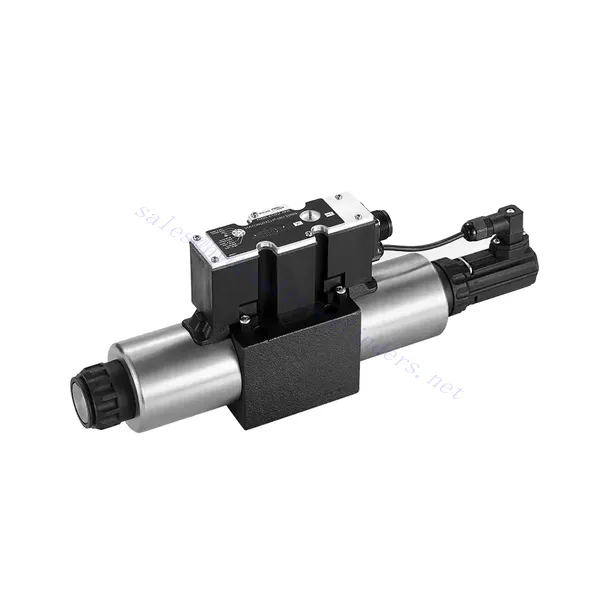
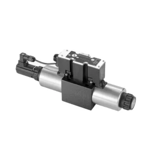
4WRE(E) Series Proportional Directional Hydraulic Valve
Yhtenä hydraulisylinterien valmistajista, toimittajista ja mekaanisten tuotteiden viejistä tarjoamme hydraulisylintereitä ja monia muita tuotteita.
Ota yhteyttä meihin saadaksesi lisätietoja.
Posti:sales@hydraulic-cylinders.net
Valmistaja toimittaja viejä hydraulisylinterit.
4WRE(E) Series Proportional Directional Hydraulic Valve
The 4WRE(E) series proportional directional hydraulic valve is a cutting-edge hydraulic component designed to deliver precise control and exceptional performance in hydraulic systems. This valve utilizes advanced proportional control technology to ensure accurate flow regulation and seamless directional changes.
The 4WRE(E) series proportional directional hydraulic valve empowers hydraulic systems with precise flow control, versatile directional changes, and energy efficiency. Its proportional control technology enables accurate and responsive flow adjustment, while the high flow capacity ensures reliable performance even in demanding applications. By following the recommended usage methods and maintenance guidelines, you can maximize the benefits and longevity of the 4WRE(E) series valve, elevating your hydraulic system to new levels of precision and performance. Upgrade your hydraulic setup today and experience the power of the 4WRE(E) series proportional directional hydraulic valve.
4WRE(E) Series Proportional Directional Hydraulic Valve Key Characteristics:
- Proportional Control Technology:
- The 4WRE(E) series valve features advanced proportional control technology, allowing for precise and proportional flow adjustment according to control signals.
- This feature enables accurate and responsive control, resulting in improved system performance and efficiency.
- Versatile Directional Control:
- With its proportional directional control capability, this valve offers versatile control over hydraulic fluid direction.
- It allows for seamless activation and deactivation of hydraulic components such as cylinders, motors, and actuators in different directions, enhancing system flexibility and productivity.
- Suuri virtauskapasiteetti:
- The 4WRE(E) series valve is designed to handle high flow rates, making it suitable for applications requiring substantial hydraulic power.
- Sen kestävä rakenne varmistaa luotettavan suorituskyvyn myös vaativissa olosuhteissa ja tarjoaa tasaisen ja tehokkaan virtauksen hallinnan.
- Energiatehokkuus:
- By employing advanced flow control mechanisms, this valve minimizes pressure drops and optimizes energy usage.
- It helps reduce energy consumption, resulting in cost savings and environmental benefits.
4WRE(E) Series Proportional Directional Hydraulic Valve Parameter:
| Hydraulinen | ||||
| Asennusasento | optional, preferably horizontal | |||
| Koko | 6 | 10 | ||
| Paino | 4WRE…L2X | Kg | 2.2 | 6.3 |
| 4WREE…L2X | 2.4 | 6.5 | ||
| Nominal flow qnom at Δp = 10 bar | L/min | 8 16 32 | 25 50 75 | |
| Hystereesi | % | ≤0.1 | ||
| Reversal span | % | ≤0.05 | ||
| Toistettavuus | % | ≤0.05 | ||
| Maks. käyttöpaine | Port s A B P | baari | 315 | |
| Portti T | baari | 210 | ||
| Neste | Mineraaliöljy, joka sopii NBR- ja FKM-tiivisteille | |||
| Fosfaattiesteri FKM-tiivisteelle | ||||
| Ambient air temperature range | 4WRA…L2X | ℃ | -20℃ to 70℃ (-4°F to 158°F) | |
| 4WRAE…L2X | ℃ | -20℃ to 50℃ (-4°F to 122°F) | ||
| Viskositeettialue | mm²/s | 20 to 380 (preferably 30 to 46) | ||
| Saastumisaste | NAS1638 class9 or ISO 4406 class 20/18/15 | |||
| Sähkötiedot | ||||
| 1)solenoid | ||||
| Koko | 6 | 10 | ||
| Voltage type | DC | |||
| Command value signal | ±10V or 4~20mA | |||
| Max.current per solenoid | A | 2.5 | ||
| Käämin vastus | Cold value | Ω | 2.7 | 3.7 |
| Max. warm value | 4.05 | 5.55 | ||
| Duty | % | ED 100% | ||
| Coil temperature | ℃ | 150 | ||
| Valve protection to EN 60529 | IP65 | |||
| 2) Control electronics | ||||
| Vahvistin | 4WRE…L2X | VT-VSPA2-L2X | ||
| 4WREE…L2X | integrated(OBE) | |||
| Operating voltage | Nominal voltage | VDC | 24 | |
| Lower limiting value | V | 19.4 | ||
| Upper limiting value | V | 35 | ||
| Amplifier current consumption | Imax | A | < 2 | |
| Imax | A | 3 | ||
4WRE(E) Series Proportional Directional Hydraulic Valve Advantages:
• Direct-acting proportional directional valve, used to control the flow and direction of liquid flow
• Panel type installation
• The proportional solenoid actuates the valve core through the threaded connection, and the coil can be removed separately
• Spool position feedback
• Optional with built-in amplifier, 4WRAE…L2X type input can be A1 or F1
• Supporting supply of external amplifier
Usage Method Of 4WRE(E) Series Proportional Directional Hydraulic Valve:
- Järjestelmän arviointi:
- Arvioi hydraulijärjestelmäsi ja määritä erityiset virtaus- ja suunnansäätövaatimukset.
- Determine if the 4WRE(E) series valve is suitable based on its flow capacity, pressure rating, and compatibility with your system.
- Venttiilin valinta:
- Select the appropriate variant of the 4WRE(E) series valve based on your system parameters, flow requirements, and directional control needs.
- Ota huomioon tekijät, kuten suurin virtausnopeus, paineluokitus, vasteaika ja käyttöolosuhteet.
- Asennus:
- Noudata valmistajan asennusohjeita huolellisesti ja varmista venttiilin oikea kohdistus ja tukeva kiinnitys.
- Tee vuotamattomat liitännät ja varmista oikea virtaussuunta optimaalisen suorituskyvyn takaamiseksi.
- Ohjaussignaalin liitäntä:
- Kytke venttiilin ohjaussignaalijohtimet sopivaan ohjauslaitteeseen, kuten proportionaalivahvistimeen tai elektroniseen ohjausyksikköön.
- Varmista venttiilin ja ohjauslaitteen oikea johdotus ja yhteensopivuus tarkan ja reagoivan ohjauksen varmistamiseksi.
How To Adjust Valves With Hydraulic Lifters?
Adjusting valve lash on hydraulic lifters is a crucial maintenance task to ensure proper engine performance and prevent issues such as noisy valves or reduced power. Here’s a step-by-step guide on how to adjust valve lash on hydraulic lifters:
- Valmistelu:
- Ensure the engine is off and cool before starting the adjustment process.
- Familiarize yourself with the engine’s firing order and the specific valve lash specifications provided by the manufacturer for your engine model.
- Identify the Correct Cylinder:
- Locate the firing position of the engine by referring to the engine’s firing order diagram.
- Identify the cylinder that corresponds to the specific valve you want to adjust.
- Sylinterin sijoittaminen:
- Rotate the engine crankshaft manually using a socket wrench or the engine’s built-in turning mechanism.
- Position the cylinder you want to adjust at the top dead center (TDC) on the compression stroke. You can do this by aligning the timing marks on the crankshaft pulley or using a piston stop tool.
- Loosen the Rocker Arm:
- Locate the rocker arm on the specific valve you want to adjust.
- Loosen the rocker arm nut or adjuster screw using an appropriate wrench or socket.
- Adjust the Valve Lash:
- With the rocker arm loose, you can now adjust the valve lash. The valve lash is the clearance between the rocker arm and the valve stem.
- Use a feeler gauge to measure the existing valve lash. Insert the appropriate thickness gauge between the rocker arm and the valve stem.
- If the clearance is too tight, meaning the feeler gauge does not fit or has excessive resistance, you need to increase the valve lash. If the clearance is too loose, meaning the feeler gauge slides in too easily, you need to decrease the valve lash.
- To adjust the valve lash, tighten or loosen the rocker arm nut or adjuster screw accordingly. Refer to the manufacturer’s specifications for the recommended amount of adjustment to be made.
- Recheck the Valve Lash:
- After making the adjustment, recheck the valve lash using the feeler gauge to ensure it falls within the recommended specifications.
- Repeat the adjustment process if necessary until the correct valve lash is achieved.
- Repeat for Other Cylinders:
- Proceed to the next cylinder in the firing order and repeat steps 4 to 6 for each cylinder you want to adjust.
- Remember to rotate the crankshaft and position each cylinder at TDC on the compression stroke before adjusting its valve lash.
- Secure the Rocker Arm:
- Once the valve lash is properly adjusted for each cylinder, tighten the rocker arm nut or adjuster screw to the manufacturer’s recommended torque specification.
- Double-check that the valve lash remains within the specified range after tightening.
- Lopputarkastukset:
- Rotate the engine crankshaft a few times to ensure smooth rotation and check for any unusual noises or resistance.
- Start the engine and listen for any abnormal valve noises. If you hear excessive tapping or knocking, recheck the valve lash adjustment.
Tehtaan kapasiteetti ja kapasiteetti:
(1) Kokoonpano
Meillä on ensiluokkainen riippumaton tutkimus- ja kehitystyön kokoonpanoalusta. Hydraulisylinterien tuotantopajassa on neljä puoliautomaattista nostosylinterin kokoonpanolinjaa ja yksi automaattinen kallistussylinterin kokoonpanolinja, joiden suunniteltu vuotuinen tuotantokapasiteetti on 1 miljoona kappaletta. Erikoissylinterin työpaja on varustettu erilaisilla eritelmillä puoliautomaattisen puhdistusasennuksen kokoonpanojärjestelmällä, jonka suunniteltu vuotuinen tuotantokapasiteetti on 200 000, ja se on varustettu kuuluisilla CNC-työstölaitteilla, työstökeskuksella, korkean tarkkuuden sylinterin käsittelyyn tarkoitetuilla erityislaitteilla, robottihitsauskoneella, automaattisella puhdistuslaitteella, automaattisella sylinterin kokoonpanokoneella ja automaattisella maalaustuotantolinjalla. Olemassa olevat kriittiset laitteet yli 300 sarjaa (sarjaa). Laiteresurssien optimaalinen kohdentaminen ja tehokas käyttö varmistavat tuotteiden tarkkuusvaatimukset ja täyttävät tuotteiden laatuvaatimukset.


(2) Koneistus
Työstöpaja on varustettu räätälöidyllä kaltevalla kiskosorvauskeskuksella, työstökeskuksella, suurnopeus-hiontakoneella, hitsausrobotilla ja muilla vastaavilla laitteilla, joilla voidaan käsitellä sylinteriputkia, joiden sisähalkaisija on enintään 400 mm ja enimmäispituus on 6 metriä.

(3) Hitsaus

(4) Maalaus ja pinnoitus
Pienillä ja keskisuurilla sylinterin automaattisilla vesipohjaisilla maalipinnoituslinjoilla automaattisen robotin lastaus- ja purku- ja automaattisen ruiskutuksen saavuttamiseksi, suunnittelukapasiteetti on 4000 kappaletta vuorossa;
Meillä on myös puoliautomaattinen maalauslinja suurille sylintereille, joka toimii voimaketjulla ja jonka suunnittelukapasiteetti on 60 laatikkoa työvuorossa.


(5) Testaus
Meillä on ensiluokkaiset tarkastustilat ja testialustat, joilla varmistetaan, että sylinterin suorituskyky täyttää vaatimukset.

Olemme yksi parhaista hydraulisylintereiden valmistajista. Voimme tarjota kattavia hydraulisylintereitä. Tarjoamme myös vastaavia maatalousvaihteistotOlemme vieneet tuotteitamme asiakkaille maailmanlaajuisesti ja ansainneet hyvän maineen erinomaisen tuotelaadun ja huoltopalvelumme ansiosta. Toivotamme tervetulleeksi asiakkaat kotimaassa ja ulkomailla ottamaan meihin yhteyttä neuvotellakseen liiketoimista, vaihtaakseen tietoja ja tehdä yhteistyötä kanssamme!
Hydraulisylinteri Sovellus:
