
50SD58-40 Solenoid Directional Valve
Yhtenä hydraulisylinterien valmistajista, toimittajista ja mekaanisten tuotteiden viejistä tarjoamme hydraulisylintereitä ja monia muita tuotteita.
Ota yhteyttä meihin saadaksesi lisätietoja.
Posti:sales@hydraulic-cylinders.net
Valmistaja toimittaja viejä hydraulisylinterit.
50SD58-40 Solenoid Directional Valve
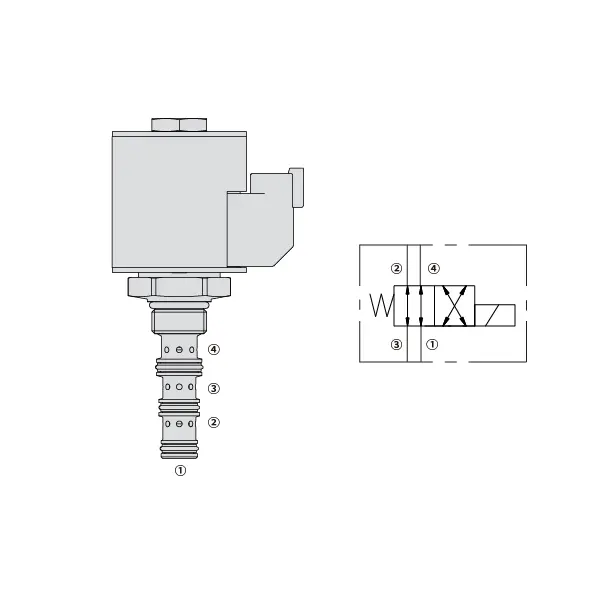
The 50sd58-40 solenoid directional valve is a cutting-edge and versatile component designed to revolutionize fluid control systems. With its exceptional performance and precise flow control capabilities, this valve is the ultimate solution for a wide range of industrial applications. From manufacturing to automation and beyond, the 50sd58-40 solenoid directional valve delivers unparalleled control and reliability.
The 30SD16-22 solenoid directional valve is essential for precise fluid control in industrial applications. Its robust construction, efficient performance, and versatility make it an ideal choice for many fluid control systems. Proper maintenance will ensure its optimal functionality and longevity. Invest in the 30SD16-22 solenoid directional valve to enhance fluid control operations and achieve exceptional results.
50SD58-30 Solenoid Directional Valve Characteristics:
- Ylivertainen rakenne: Crafted with the highest quality materials, the 50SD58-40 Solenoid Directional Valve is built to withstand the most demanding environments. Its robust construction ensures durability, longevity, and resistance to wear, corrosion, and extreme operating conditions.
- Optimal Flow Control: This valve offers exceptional flow control capabilities, allowing for precise adjustment of fluid rates. With excellent repeatability and rapid response times, it ensures accurate and efficient control over fluid flow, enhancing the overall performance of your system.
- Versatile Configuration: The 50SD58-40 Solenoid Directional Valve is available in various configurations, including inline, manifold, or subplate mounting options. This versatility allows for seamless integration into different fluid control systems, making it suitable for a wide range of applications.
- Luotettava suorituskyky: Engineered to deliver consistent and reliable performance, this valve is built to meet the highest industry standards. Its advanced design and meticulous manufacturing ensure optimal functionality and dependable operation, reducing downtime and maintenance costs.
50SD58-30 Solenoid Directional Valve Parameter:
| Nimellispaine | 345 bar(5000 psi) | |
| Huippuvirtaus | Katso suorituskykykaavio | |
| Neste | Mineraalipohjaiset tai synteettiset voiteluominaisuudet | |
| Nesteen lämpötila-alue ℃ | -54 to 107 ℃ (Polyurethane seals) | |
| -40 - 100 ℃ (Buna N -tiivisteet) | ||
| -26 - 204 ℃ (fluorihiilitiivisteet) | ||
| Viskositeettialue | 7,4–420 mm2/s | |
| Saastumisaste | Minimipäästötaso on ISO4406-taso 18/16/13, ja käyttöiän pidentämiseksi suositellaan tasoa 15/13/11. | |
| Sisäinen vuoto | ≤ 180 mL/min@345bar | |
| Ontelo | VC08-4 | |
| Käämin käyttöikä | Jatkuva nimellisjännitteellä 85% - 115% | |
| Alkuperäinen kelan virrankulutus 20 ℃:ssa | Sähkökela | 1,7 A 12 VDC:n jännitteellä; 0,85 A 24 VDC:n jännitteellä |
| D-kela | 1,67 A 12 VDC:n jännitteellä; 0,83 A 24 VDC:n jännitteellä | |
| Minimivetojännite | 85% of nominal at 345 bar (3000 psi) | |
50SD58-30 Solenoid Directional Valve Advantages:
• Jatkuvatoiminen kela
• Äänirasiat ovat jännitteeltään vaihdettavissa
• Lisävarusteena vedenpitävät E-kelat, joiden luokitus on jopa IP69K
• Tehokas märkärakenteinen rakenne
• Karkaistut osat pitkän käyttöiän takaamiseksi
Usage Method Of 50SD58-30 Solenoid Directional Valve:
- Järjestelmän arviointi: Analyze your fluid control system’s requirements, including pressure, flow rate, and directional control needs. Verify that the 50SD58-40 Solenoid Directional Valve matches the specifications and is compatible with your application.
- Asennus ja liitäntä: Select the appropriate mounting method based on your system layout and available space. Install the valve securely, ensuring proper alignment with the fluid lines. Connect the valve to the system using compatible fittings and connectors, ensuring tight and leak-free connections.
- Sähköliitäntä: Following the manufacturer’s instructions, connect the valve’s solenoid to the appropriate power supply. Ensure correct wiring and adhere to safety guidelines during the electrical connection process.
- Testing and Adjustment: Gradually introduce fluid flow to the system and monitor the valve’s performance. Test different operating conditions, including pressure and flow variations, and adjust the valve settings to achieve optimal control and system functionality.
How To Replace Delta Single Handle Valve Cartridge?
Replacing the cartridge in a Delta single-handle valve is a relatively straightforward process that can help resolve issues such as leaks or temperature control problems. Here’s a step-by-step guide on how to replace a Delta single-handle valve cartridge:
- Gather the necessary tools: Before you begin, make sure you have the following tools ready: adjustable wrench, Phillips screwdriver, needle-nose pliers, and a replacement cartridge specific to your Delta single-handle valve model.
- Turn off the water supply: Locate the main water shut-off valve for your home and turn it off to stop the water flow to the shower or faucet. If there is no dedicated shut-off valve for the bathroom, you may need to shut off the main water supply.
- Remove the handle: Locate the set screw on the handle, usually located under a decorative cap or button. Use a Phillips screwdriver to remove the set screw, then pull the handle straight off.
- Remove the trim sleeve and escutcheon plate: Next, remove the trim sleeve and escutcheon plate, which are usually located around the valve body. These components may be threaded or held in place with screws. Unscrew or remove any screws and gently pull or twist the sleeve and escutcheon plate to detach them from the wall.
- Remove the bonnet nut: The bonnet nut secures the cartridge in place. Use an adjustable wrench to loosen and remove the bonnet nut by turning it counterclockwise. Be cautious not to damage the surrounding plumbing or valve body.
- Remove the old cartridge: Once the bonnet nut is removed, you can now pull the old cartridge straight out of the valve body. If it’s stuck, you can use needle-nose pliers or a cartridge removal tool for added leverage.
- Install the new cartridge: Take the replacement Delta cartridge and align it with the valve body, ensuring that any tabs or notches match up correctly. Gently push the cartridge into the valve body until it fits snugly.
- Reassemble the valve: Once the new cartridge is installed, reassemble the valve by following the steps in reverse order. Place the bonnet nut back onto the valve body and tighten it with an adjustable wrench. Be careful not to overtighten.
- Reinstall the trim sleeve, escutcheon plate, and handle: Slide the trim sleeve and escutcheon plate back onto the valve body and secure them in place with screws or by threading them back on. Finally, reattach the handle by aligning it with the cartridge stem and securing it with the set screw.
- Test for leaks and functionality: Turn the water supply back on and test the shower or faucet. Check for any leaks around the valve and ensure that the hot and cold water controls are working correctly. If necessary, make any adjustments to the cartridge or connections to resolve any issues.
Tehtaan kapasiteetti ja kapasiteetti:
(1) Kokoonpano
Meillä on ensiluokkainen riippumaton tutkimus- ja kehitystyön kokoonpanoalusta. Hydraulisylinterien tuotantopajassa on neljä puoliautomaattista nostosylinterin kokoonpanolinjaa ja yksi automaattinen kallistussylinterin kokoonpanolinja, joiden suunniteltu vuotuinen tuotantokapasiteetti on 1 miljoona kappaletta. Erikoissylinterin työpaja on varustettu erilaisilla eritelmillä puoliautomaattisen puhdistusasennuksen kokoonpanojärjestelmällä, jonka suunniteltu vuotuinen tuotantokapasiteetti on 200 000, ja se on varustettu kuuluisilla CNC-työstölaitteilla, työstökeskuksella, korkean tarkkuuden sylinterin käsittelyyn tarkoitetuilla erityislaitteilla, robottihitsauskoneella, automaattisella puhdistuslaitteella, automaattisella sylinterin kokoonpanokoneella ja automaattisella maalaustuotantolinjalla. Olemassa olevat kriittiset laitteet yli 300 sarjaa (sarjaa). Laiteresurssien optimaalinen kohdentaminen ja tehokas käyttö varmistavat tuotteiden tarkkuusvaatimukset ja täyttävät tuotteiden laatuvaatimukset.


(2) Koneistus
Työstöpaja on varustettu räätälöidyllä kaltevalla kiskosorvauskeskuksella, työstökeskuksella, suurnopeus-hiontakoneella, hitsausrobotilla ja muilla vastaavilla laitteilla, joilla voidaan käsitellä sylinteriputkia, joiden sisähalkaisija on enintään 400 mm ja enimmäispituus on 6 metriä.

(3) Hitsaus

(4) Maalaus ja pinnoitus
Pienillä ja keskisuurilla sylinterin automaattisilla vesipohjaisilla maalipinnoituslinjoilla automaattisen robotin lastaus- ja purku- ja automaattisen ruiskutuksen saavuttamiseksi, suunnittelukapasiteetti on 4000 kappaletta vuorossa;
Meillä on myös puoliautomaattinen maalauslinja suurille sylintereille, joka toimii voimaketjulla ja jonka suunnittelukapasiteetti on 60 laatikkoa työvuorossa.


(5) Testaus
Meillä on ensiluokkaiset tarkastustilat ja testialustat, joilla varmistetaan, että sylinterin suorituskyky täyttää vaatimukset.

Olemme yksi parhaista hydraulisylintereiden valmistajista. Voimme tarjota kattavia hydraulisylintereitä. Tarjoamme myös vastaavia maatalousvaihteistotOlemme vieneet tuotteitamme asiakkaille maailmanlaajuisesti ja ansainneet hyvän maineen erinomaisen tuotelaadun ja huoltopalvelumme ansiosta. Toivotamme tervetulleeksi asiakkaat kotimaassa ja ulkomailla ottamaan meihin yhteyttä neuvotellakseen liiketoimista, vaihtaakseen tietoja ja tehdä yhteistyötä kanssamme!
Hydraulisylinteri Sovellus:
