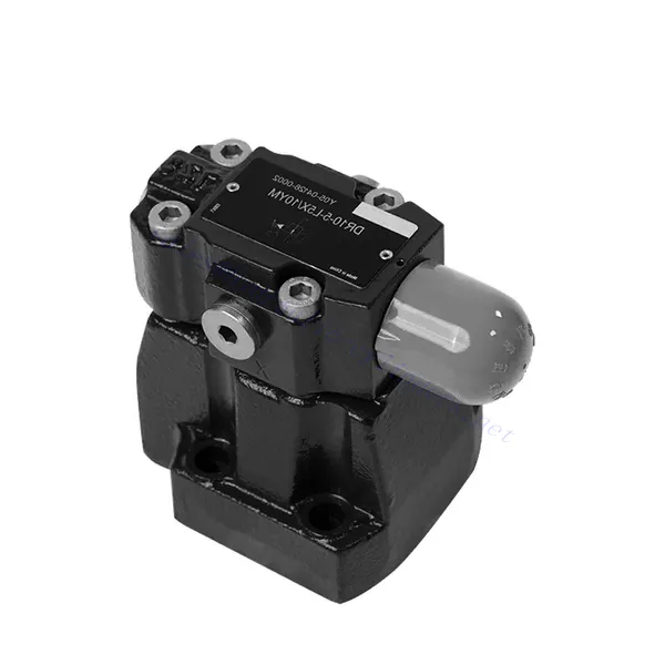
DR Series Pilot Operated Pressure Reducing Hydraulic Valve
Yhtenä hydraulisylinterien valmistajista, toimittajista ja mekaanisten tuotteiden viejistä tarjoamme hydraulisylintereitä ja monia muita tuotteita.
Ota yhteyttä meihin saadaksesi lisätietoja.
Posti:sales@hydraulic-cylinders.net
Valmistaja toimittaja viejä hydraulisylinterit.
DR Series Pilot Operated Pressure Reducing Hydraulic Valve
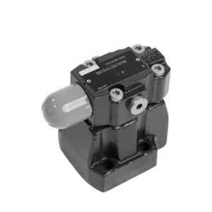
The DR series pilot-operated pressure-reducing hydraulic valve is a high-quality and reliable component designed to provide precise pressure control in hydraulic systems. With its innovative pilot-operated mechanism and exceptional performance, this valve accurately reduces hydraulic pressure to meet specific system requirements.
The DR series pilot-operated pressure-reducing hydraulic valve is a high-performance solution for precise pressure control in hydraulic systems. With its pilot-operated design, precise pressure control, wide pressure range, and high flow capacity, this valve ensures efficient and accurate pressure reduction while safeguarding system components. Following the recommended usage methods and maintenance practices, the DR series valve delivers reliable performance, extending the lifespan of hydraulic systems. Upgrade your hydraulic system with the dr series pilot-operated pressure-reducing hydraulic valve and experience optimal pressure control for enhanced system efficiency and productivity.
DR Series Pilot Operated Pressure Reducing Hydraulic Valve Key Characteristics:
- Pilottiohjattu suunnittelu:
- The DR series valve features a pilot-operated design, providing accurate, reliable, and stable pressure reduction in hydraulic systems.
- It utilizes a separate control circuit, the pilot circuit, to regulate the main valve’s opening and control the pressure.
- Tarkka paineensäätö:
- This valve offers exceptional precision in pressure control, allowing hydraulic systems to operate within desired pressure limits.
- Se ylläpitää tasaisia painetasoja estäen ylipaineistuksen ja suojaten herkkiä järjestelmäkomponentteja.
- Laaja painealue:
- The DR series valve is available in various pressure ranges, making it suitable for various hydraulic applications.
- Se mahdollistaa mukauttamisen vastaamaan tiettyjä järjestelmävaatimuksia ja optimoimaan suorituskyvyn.
- Suuri virtauskapasiteetti:
- This valve exhibits excellent flow capacity, enabling it to handle high flow rates without compromising pressure control accuracy.
- Se varmistaa tehokkaan nesteen säätelyn ja järjestelmän keskeytymättömän toiminnan.
DR Series Pilot Operated Pressure Reducing Hydraulic Valve Parameter:
| Neste | Mineraaliöljy, joka sopii NBR- ja FKM-tiivisteille | |||||||
| Fosfaattiesteri FKM-tiivisteelle | ||||||||
| Nesteen lämpötila-alue | ℃ | -30 to +80 (NBR seals) | ||||||
| -20 to +80(FKM seals) | ||||||||
| Viskositeettialue | mm2/s | 10–800 | ||||||
| Saastumisaste | Suurin sallittu nesteen kontaminaatioaste: Luokka 9. NAS 1638 tai 20/18/15, ISO4406 | |||||||
| Maks. käyttöpaine | Port B | baari | 350 | |||||
| Operating pressure range | Port A | baari | 10 to 350 | |||||
| Max.backing pressure | Portti Y | baari | 350 (only for without check valve); 315 (with check valve) | |||||
| Paineen asettaminen | Max. | baari | 50;100;200;315;350 | |||||
| Min. | baari | Related with flow-rate(Refer to the characteristic curve) | ||||||
| Koko | DR10 | DR15 | DR20 | DR25 | DR30 | |||
| Maks. virtausnopeus | Base sub-plate mounting | L/min | 150 | – | 300 | – | 400 | |
| threaded connection | L/min | 150 | 300 | 300 | 400 | 400 | ||
| Asennusasento | Asennusasento | |||||||
| Koko | DR10 | DR15 | DR20 | DR25 | DR30 | |||
| Paino | Base Sub-plate mounting | DR | kg | about 3.6 | – | about 5.3 | – | about 8.2 |
| threaded connection | DR…G | kg | about 5.3 | about 5.5 | about 5.1 | about 5.0 | about 5.0 | |
| DRC | kg | noin 1,2 | ||||||
| DRC30 | kg | about 1.5 | ||||||
DR Series Pilot Operated Pressure Reducing Hydraulic Valve Advantages:
• Käytetään pohjalevyn asennukseen
• Installation face follow DIN24340 D and ISO5781
• Käytetään öljypolkujen lohkojen asennuksessa
• Käytetään ruuviliitoksissa
• Viisi painealuetta
• Kaksi säätötyyppiä: nuppi, säätöruuvi suojakorkilla
• Optional one directional valve ( only used for bottom sub-plate mounting )
Usage Method Of DR Series Pilot Operated Pressure Reducing Hydraulic Valve :
- Järjestelmäanalyysi:
- Suorita kattava hydrauliikkajärjestelmän analyysi määrittääksesi erityiset paineensäätövaatimukset.
- Ota huomioon suurin käyttöpaine, haluttu painealue ja virtausnopeudet.
- Venttiilin valinta:
- Select the appropriate DR series valve variant based on the system’s pressure control specifications.
- Ota huomioon paineluokitus, virtauskapasiteetti ja yhteensopivuus muiden järjestelmäkomponenttien kanssa.
- Asennus:
- Follow the manufacturer’s instructions to correctly install the hydraulic system’s DR series pilot-operated pressure-reducing valve.
- Varmista oikea kohdistus ja turvalliset liitännät vuotojen estämiseksi ja suorituskyvyn optimoimiseksi.
- Kalibrointi:
- Calibrate the valve to set the desired downstream pressure.
- Utilize pressure gauges or other measurement devices to adjust the valve’s pilot circuit accurately.
How Does A Hydraulic Relief Valve Work?
A hydraulic relief valve is a crucial component in hydraulic systems that protects the system from excessive pressure by diverting excess fluid flow back to the reservoir. It operates based on the principle of utilizing a spring-loaded mechanism to control the pressure level within the system. Let’s explore how a hydraulic relief valve works:
- Venttiilin rakenne:
- A hydraulic relief valve consists of a valve body, a spring-loaded poppet or spool, and an adjustable spring.
- The valve body contains fluid ports for the inlet, outlet, and a drain or return line to the reservoir.
- Paineen asetus:
- The relief valve has an adjustable spring that determines the pressure at which the valve opens.
- Adjusting the spring tension can set the pressure to open the valve and relieve excess stress.
- System Pressure Monitoring:
- As the hydraulic system operates, the pressure builds up due to factors such as pump output, load resistance, or temperature changes.
- The relief valve continuously monitors the system pressure through its inlet port.
- Pressure Threshold:
- When the system pressure reaches or exceeds the set pressure threshold, a force is exerted on the poppet or spool against the spring tension.
- Venttiilin aukko:
- Once the force exerted by the system pressure exceeds the spring tension, the relief valve opens.
- This creates a path for excess fluid to flow from the system’s high-pressure side to the low-pressure side or directly back to the reservoir.
- Pressure Equalization:
- The relief valve diverts the excess fluid flow, allowing the pressure within the system to equalize and preventing over-pressurization.
- This protects system components from potential damage and ensures safe operation.
- Closing the Valve:
- Once the pressure drops below the set threshold, the spring’s tension overcomes the force exerted by the system pressure.
- The relief valve closes, blocking the fluid flow path and restoring the normal flow of hydraulic fluid through the system.
- Continuous Monitoring:
- The relief valve continuously monitors the system pressure, opening and closing as necessary to maintain pressure within the desired range.
- This dynamic response ensures that the system operates safely and prevents pressure spikes or fluctuations.
Tehtaan kapasiteetti ja kapasiteetti:
(1) Kokoonpano
Meillä on ensiluokkainen riippumaton tutkimus- ja kehitystyön kokoonpanoalusta. Hydraulisylinterien tuotantopajassa on neljä puoliautomaattista nostosylinterin kokoonpanolinjaa ja yksi automaattinen kallistussylinterin kokoonpanolinja, joiden suunniteltu vuotuinen tuotantokapasiteetti on 1 miljoona kappaletta. Erikoissylinterin työpaja on varustettu erilaisilla eritelmillä puoliautomaattisen puhdistusasennuksen kokoonpanojärjestelmällä, jonka suunniteltu vuotuinen tuotantokapasiteetti on 200 000, ja se on varustettu kuuluisilla CNC-työstölaitteilla, työstökeskuksella, korkean tarkkuuden sylinterin käsittelyyn tarkoitetuilla erityislaitteilla, robottihitsauskoneella, automaattisella puhdistuslaitteella, automaattisella sylinterin kokoonpanokoneella ja automaattisella maalaustuotantolinjalla. Olemassa olevat kriittiset laitteet yli 300 sarjaa (sarjaa). Laiteresurssien optimaalinen kohdentaminen ja tehokas käyttö varmistavat tuotteiden tarkkuusvaatimukset ja täyttävät tuotteiden laatuvaatimukset.


(2) Koneistus
Työstöpaja on varustettu räätälöidyllä kaltevalla kiskosorvauskeskuksella, työstökeskuksella, suurnopeus-hiontakoneella, hitsausrobotilla ja muilla vastaavilla laitteilla, joilla voidaan käsitellä sylinteriputkia, joiden sisähalkaisija on enintään 400 mm ja enimmäispituus on 6 metriä.

(3) Hitsaus

(4) Maalaus ja pinnoitus
Pienillä ja keskisuurilla sylinterin automaattisilla vesipohjaisilla maalipinnoituslinjoilla automaattisen robotin lastaus- ja purku- ja automaattisen ruiskutuksen saavuttamiseksi, suunnittelukapasiteetti on 4000 kappaletta vuorossa;
Meillä on myös puoliautomaattinen maalauslinja suurille sylintereille, joka toimii voimaketjulla ja jonka suunnittelukapasiteetti on 60 laatikkoa työvuorossa.


(5) Testaus
Meillä on ensiluokkaiset tarkastustilat ja testialustat, joilla varmistetaan, että sylinterin suorituskyky täyttää vaatimukset.

Olemme yksi parhaista hydraulisylintereiden valmistajista. Voimme tarjota kattavia hydraulisylintereitä. Tarjoamme myös vastaavia maatalousvaihteistotOlemme vieneet tuotteitamme asiakkaille maailmanlaajuisesti ja ansainneet hyvän maineen erinomaisen tuotelaadun ja huoltopalvelumme ansiosta. Toivotamme tervetulleeksi asiakkaat kotimaassa ja ulkomailla ottamaan meihin yhteyttä neuvotellakseen liiketoimista, vaihtaakseen tietoja ja tehdä yhteistyötä kanssamme!
Hydraulisylinteri Sovellus:
