

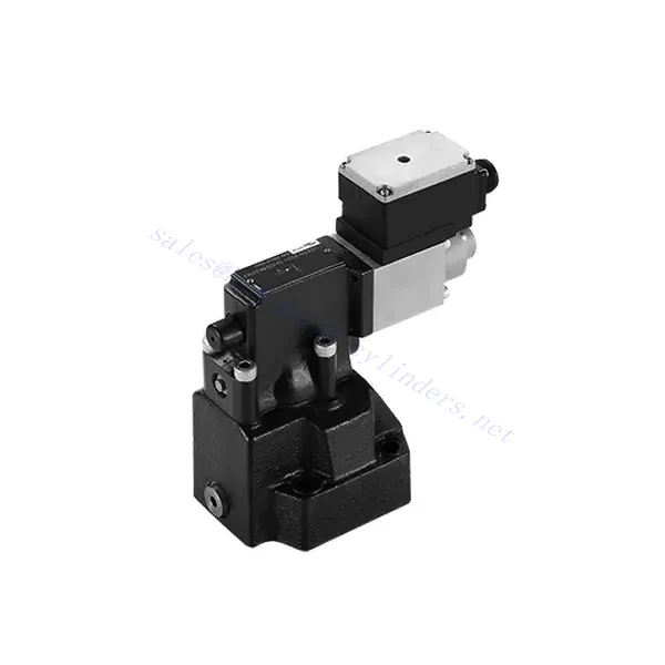
DRE(E) Series Proportional Pressure Reducing Valve

The DRE(E) series proportional pressure reducing valve is a state-of-the-art hydraulic component that delivers precise and reliable pressure control in various industrial applications. With its advanced features, exceptional performance, and robust construction, this valve offers a solution that optimizes system efficiency and enhances productivity.
The DRE(E) series proportional pressure reducing valve offers precise and reliable pressure control for hydraulic systems. With exceptional proportional control, pressure reduction function, high flow capacity, and fast response time, this valve provides accurate pressure regulation and safeguards downstream components. By following the recommended usage methods and maintenance guidelines, you can harness the full potential of this valve and achieve enhanced performance in your hydraulic applications. Upgrade your hydraulic system today with the DRE(E) series proportional pressure reducing valve and experience optimal pressure control with precision and reliability.
DRE(E) Series Proportional Pressure Reducing Valve Key Characteristics:
- Proportionaalinen säätö:
- The DRE(E) series valve boasts exceptional proportional control capabilities, enabling precise adjustment of pressure levels.
- This advanced control feature ensures accurate pressure regulation tailored to specific system requirements, promoting efficient and optimized performance.
- Pressure Reduction Function:
- Equipped with a pressure reduction function, this valve efficiently lowers the incoming pressure to a predefined setpoint.
- By accurately reducing the pressure, the valve protects downstream components, preventing damage and ensuring stable system operation.
- Suuri virtauskapasiteetti:
- The DRE(E) series valve is designed to handle high flow rates, making it suitable for applications that require substantial fluid volumes.
- Its high flow capacity enables efficient operation even in demanding industrial environments.
- Nopea vasteaika:
- With an impressive response time, this valve allows for rapid adjustments to pressure changes within the system.
- The fast response ensures precise control, minimizing pressure fluctuations and promoting stable and consistent system performance.
DRE(E) Series Proportional Pressure Reducing Valve Parameter:
| Yleistä | |||||
| Neste | Mineraaliöljy, joka sopii NBR- ja FKM-tiivisteille | ||||
| Fosfaattiesteri FKM-tiivisteelle | |||||
| Nesteen lämpötila-alue | ℃ | -30 - +80 (NBR-tiiviste) | |||
| -20 - +80 (FKM-tiiviste) | |||||
| Viskositeettialue | mm2/s | 2,8–380 | |||
| Saastumisaste | Suurin sallittu nesteen kontaminaatioaste: Luokka 9. NAS 1638 tai 20/18/15, ISO4406 | ||||
| Maks. käyttöpaine | Port A,B | baari | 315 | ||
| Portti Y | Separate and at zero pressure to tank | ||||
| Suurin asetuspaine | Port A | baari | 50; 100; 200; 315 | ||
| Min. säädettävä paine | Port A | Virtauksen (Q) osalta katso ominaiskäyrät | |||
| Pressure at current value 0 in port A | =Min. settable pressure (Refer to the characteristic curve ) | ||||
| Maksimipaineen turvallisuus (portaattomasti säädettävä) | Paineen asettaminen | Painealue enimmäisturvapaineen rajoissa | |||
| 50 baaria | 10-60+20 bar | ||||
| 100 baaria | 10-120+20 bar | ||||
| 200 baaria | 10-220+20 bar | ||||
| 315 baaria | 10-340+20 bar | ||||
| Maksimipaineen turva-asetusehto | When rated pressure=50 bar, between 60~80 bar | ||||
| When rated pressure=100 bar, between 120~140 bar | |||||
| When rated pressure=200 bar, between 220~240 bar | |||||
| When rated pressure=315 bar, between 340~360 bar | |||||
| Koko | 10 | 25 | 32 | ||
| Maks. virtausnopeus | L/min | 80 | 200 | 300 | |
| Pilot flow-rate (for pilot valve) | L/min | 0,7–2 | |||
| Lineaarisuus | ±3,5% | ||||
| Toistettavuus | <±2% | ||||
| Hystereesi | shimmyn kanssa | ilman shimmyä | |||
| ±2.5% Pmax( 200Hz, amplitude 200mAsss) | ±4.5% Pmax | ||||
| Kytkentäaika | 100 to 300ms (undependent with the system) | ||||
| Sähkötiedot | |||||
| Voima | DC | ||||
| Solenoidin minimivirta | mA | 100 | |||
| Solenoidin maksimivirta | mA | 800 | |||
| Käämin vastus | 19.5Ω at 20℃, Max. warm value :28.8Ω | ||||
| Työskentelytila | Jatkuva | ||||
| Max. ambient temperature range | +50 ℃ | ||||
| Sähköliitäntä | Plug-in connector to DIN 43650/2+SL/PG11 | ||||
| Eristys DIN 40 050:n mukaisesti | IP65 | ||||
| Vahvistin | VT2000 | ||||
DRE(E) Series Proportional Pressure Reducing Valve Advantages:
• Käytetään pohjalevyn asennukseen
• Installation face follow DIN 24340 D and ISO 5781
• Käytetään öljypolkujen lohkojen asennuksessa
• Neljä painealuetta
• Korkeimman paineen suojausrakenne (valinnainen)
• Sopiva elektroninen vahvistin tyyppiä VT-2000 (tilattava erikseen)
Usage Method Of DRE(E) Series Proportional Pressure Reducing Valve :
- Järjestelmän arviointi:
- Evaluate your hydraulic system’s requirements, considering flow rate, pressure range, and system dynamics.
- Determine whether the proportional pressure control offered by the DRE(E) series valve aligns with your system’s needs.
- Venttiilin valinta:
- Select the appropriate variant of the DRE(E) series valve based on your system parameters and performance requirements.
- Ota huomioon tekijät, kuten virtauskapasiteetti, painealue ja yhteensopivuus muiden järjestelmäkomponenttien kanssa, optimaalisen toimivuuden varmistamiseksi.
- Asennus:
- Noudata valmistajan asennusohjeita huolellisesti varmistaaksesi venttiilin oikean sijoituksen ja turvallisen kiinnityksen.
- Aseta venttiili oikein hydraulijärjestelmään ottaen huomioon esimerkiksi nesteen virtaussuunnan ja huollon helppouden.
- Paineen asetus:
- Aseta haluttu painetaso säätämällä venttiilin ohjausmekanismia valmistajan ohjeiden mukaisesti.
- Varmista, että asetusarvo vastaa järjestelmäsi erityisvaatimuksia.
How To Remove A Shower Valve Cartridge?
Removing a shower valve cartridge may vary depending on the specific model and manufacturer. However, here is a general step-by-step guide that can help you remove a shower valve cartridge:
- Turn off the Water Supply: Locate the main water shut-off valve for your shower and turn it off to cut off the water supply. This step is essential to prevent any water flow while you work on removing the cartridge.
- Remove the Shower Handle: Most shower handles have a screw or decorative cap at the base. Look for this screw or cap and remove it using a screwdriver or by gently prying it off. Once removed, take off the handle by pulling it straight out.
- Access the Cartridge: Depending on the type of shower valve you have, you may need to remove additional parts to access the cartridge. This can include a trim plate or escutcheon that covers the valve. Use a screwdriver to remove any screws holding these parts in place and gently pull them away.
- Remove the Retaining Clip or Nut: Look for a retaining clip or nut that holds the cartridge in place. This clip or nut is usually located on the top of the cartridge and secures it to the valve body. Use pliers or an adjustable wrench to loosen and remove the clip or nut.
- Remove the Cartridge: Once the retaining clip or nut is removed, you can proceed to pull out the cartridge. Grip the cartridge firmly and pull it straight out of the valve body. If it is stuck, you may need to wiggle it gently or use a cartridge removal tool specific to your shower valve model.
- Puhdista ja tarkista: With the cartridge removed, take a moment to clean any debris or sediment from the valve body using a soft brush or cloth. Inspect the cartridge for any signs of damage or wear. If necessary, replace the cartridge with a new one that matches the model and make of your shower valve.
- Reassemble and Test: Once you have cleaned or replaced the cartridge, reassemble the shower valve by following the steps in reverse order. Make sure all parts are securely in place. Turn on the water supply and test the shower to ensure there are no leaks and that the new cartridge is functioning properly.
Tehtaan kapasiteetti ja kapasiteetti:
(1) Kokoonpano
Meillä on ensiluokkainen riippumaton tutkimus- ja kehitystyön kokoonpanoalusta. Hydraulisylinterien tuotantopajassa on neljä puoliautomaattista nostosylinterin kokoonpanolinjaa ja yksi automaattinen kallistussylinterin kokoonpanolinja, joiden suunniteltu vuotuinen tuotantokapasiteetti on 1 miljoona kappaletta. Erikoissylinterin työpaja on varustettu erilaisilla eritelmillä puoliautomaattisen puhdistusasennuksen kokoonpanojärjestelmällä, jonka suunniteltu vuotuinen tuotantokapasiteetti on 200 000, ja se on varustettu kuuluisilla CNC-työstölaitteilla, työstökeskuksella, korkean tarkkuuden sylinterin käsittelyyn tarkoitetuilla erityislaitteilla, robottihitsauskoneella, automaattisella puhdistuslaitteella, automaattisella sylinterin kokoonpanokoneella ja automaattisella maalaustuotantolinjalla. Olemassa olevat kriittiset laitteet yli 300 sarjaa (sarjaa). Laiteresurssien optimaalinen kohdentaminen ja tehokas käyttö varmistavat tuotteiden tarkkuusvaatimukset ja täyttävät tuotteiden laatuvaatimukset.


(2) Koneistus
Työstöpaja on varustettu räätälöidyllä kaltevalla kiskosorvauskeskuksella, työstökeskuksella, suurnopeus-hiontakoneella, hitsausrobotilla ja muilla vastaavilla laitteilla, joilla voidaan käsitellä sylinteriputkia, joiden sisähalkaisija on enintään 400 mm ja enimmäispituus on 6 metriä.


(3) Hitsaus


(4) Maalaus ja pinnoitus
Pienillä ja keskisuurilla sylinterin automaattisilla vesipohjaisilla maalipinnoituslinjoilla automaattisen robotin lastaus- ja purku- ja automaattisen ruiskutuksen saavuttamiseksi, suunnittelukapasiteetti on 4000 kappaletta vuorossa;
Meillä on myös puoliautomaattinen maalauslinja suurille sylintereille, joka toimii voimaketjulla ja jonka suunnittelukapasiteetti on 60 laatikkoa työvuorossa.


(5) Testaus
Meillä on ensiluokkaiset tarkastustilat ja testialustat, joilla varmistetaan, että sylinterin suorituskyky täyttää vaatimukset.


Olemme yksi parhaista hydraulisylintereiden valmistajista. Voimme tarjota kattavia hydraulisylintereitä. Tarjoamme myös vastaavia maatalousvaihteistotOlemme vieneet tuotteitamme asiakkaille maailmanlaajuisesti ja ansainneet hyvän maineen erinomaisen tuotelaadun ja huoltopalvelumme ansiosta. Toivotamme tervetulleeksi asiakkaat kotimaassa ja ulkomailla ottamaan meihin yhteyttä neuvotellakseen liiketoimista, vaihtaakseen tietoja ja tehdä yhteistyötä kanssamme!