

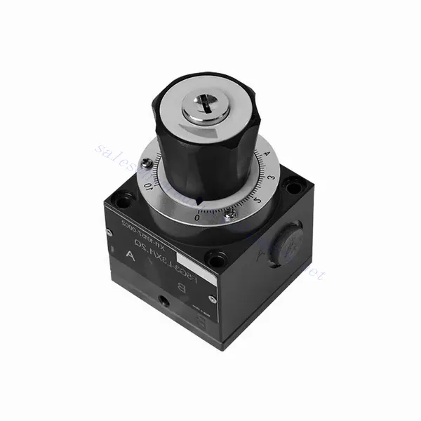
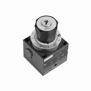
F-sarjan hienokaasuhydraulinen venttiili

F-sarjan hienosäätöinen hydraulinen venttiili on poikkeuksellinen komponentti, joka on suunniteltu tarjoamaan tarkkaa ohjausta ja parannettua tehokkuutta hydraulijärjestelmissä. Edistyksellisen hienosäätötoimintonsa ansiosta tämä venttiili tarjoaa vertaansa vailla olevan virtauksen säädön, jonka avulla käyttäjät voivat saavuttaa optimaalisen suorituskyvyn ja hallinnan hydraulisille toimilaitteille.
F-sarjan hienosäätöinen hydrauliventtiili on välttämätön komponentti hydraulijärjestelmien tarkkuuden ja hallinnan saavuttamiseksi. Edistyksellisen hienosäätötoimintonsa ansiosta tämä venttiili mahdollistaa tarkan virtauksen säädön, mikä parantaa suorituskykyä ja tehokkuutta. Noudattamalla suositeltuja käyttömenetelmiä ja huolto-ohjeita käyttäjät voivat varmistaa F-sarjan hienosäätöisen hydrauliventtiilin pitkäikäisyyden, luotettavuuden ja optimaalisen toimivuuden. Päivitä hydraulijärjestelmäsi tällä poikkeuksellisella venttiilillä ja koe parannettu tarkkuus, hallinta ja tuottavuus.
F-sarjan hienosäätöhydraulisen venttiilin tärkeimmät ominaisuudet:
- Hieno kaasun säätö:
- F-sarjan venttiili on varustettu herkällä kuristusmekanismilla, joka mahdollistaa hydraulinesteen virtausnopeuden tarkan säädön.
- Käyttäjät voivat hienosäätää virtauksen säätöä, mikä helpottaa hydraulisten toimilaitteiden tarkkaa nopeuden ja asennon säätöä.
- Parannettu suorituskyky:
- Tämä hydraulinen venttiili on erittäin suorituskykyinen tarkkojen virtauksen säätöominaisuuksiensa ansiosta.
- Varmistamalla optimaaliset virtausnopeudet F-sarjan venttiili minimoi energiahävikin, vähentää järjestelmän tehottomuutta ja maksimoi kokonaissuorituskyvyn.
- Monipuolinen käyttö:
- F-sarjan hienosäätöinen hydraulinen venttiili sopii erilaisiin hydraulijärjestelmiin ja sovelluksiin.
- Se voidaan integroida saumattomasti useille eri toimialoille, kuten teollisuuteen, maatalouteen, rakentamiseen ja muihin.
- Kestävyys ja luotettavuus:
- Korkealaatuisista materiaaleista ja kestävästä rakenteesta valmistettu venttiili on suunniteltu kestämään vaativia käyttöolosuhteita.
- Sen kestävyys varmistaa pitkäaikaisen luotettavuuden, minimoi seisokkiajat ja ylläpitokustannukset.
F-sarjan hienokaasuventtiilin hydrauliventtiilin parametri:
| Asennusasento | Valinnainen | ||
| Paino | –Jakotukin asennus | kg | 1 |
| – Kierreliitäntä | kg | 1.6 | |
| – Aluslevyn kiinnitys | kg | 1.8 | |
| Neste | Mineraaliöljy, joka sopii NBR- ja FKM-tiivisteille | ||
| Fosfaattiesteri FKM-tiivisteelle | |||
| Saastumisaste | Suurin sallittu nesteen kontaminaatioaste: Luokka 9. NAS 1638 tai 20/18/15, ISO4406 | ||
| Nesteen lämpötila-alue | ℃ | -30 - +80 (NBR-tiiviste) | |
| -20 - +80 (FKM-tiiviste) | |||
| Viskositeettialue | mm2/s | 2,8–380 | |
| Maks. käyttöpaine | baari | 210 | |
| Maks. virtausnopeus | L/min | 80 | |
| Säätökulma | ° | 300 | |
| Käyttömomentti | 100 baarissa | Nm | 1.1 |
| 200 baarissa | Nm | 1.8 | |
F-sarjan hienokaasuventtiilin edut:
• Käytetään pohjalevyn asennukseen
• Käytetään ruuviliitoksissa
• Käytetään öljypolkujen lohkojen asennuksessa
• Lukittavalla nupilla ja asteikolla
F-sarjan hienokaasuventtiilin käyttötapa:
- Järjestelmän arviointi:
- Aloita arvioimalla hydrauliikkajärjestelmä perusteellisesti ottaen huomioon virtausvaatimukset, paine-erot ja toimilaitteen tekniset tiedot.
- Määritä, tarvitaanko hienosäätöä halutun tarkkuuden ja hallinnan saavuttamiseksi.
- Venttiilin valinta:
- Valitse F-sarjan venttiilin sopiva versio järjestelmäparametrien ja tiettyjen virtauksen säätövaatimusten perusteella.
- Ota huomioon esimerkiksi suurin virtausnopeus, paineluokitus ja yhteensopivuus muiden järjestelmäkomponenttien kanssa.
- Asennus:
- Follow the manufacturer’s installation instructions carefully, ensuring accurate alignment and secure valve connections.
- Kiinnitä erityistä huomiota virtaussuunnan osoittimiin ja varmista, että liittimet ja tiivisteet on asennettu oikein.
- Hieno kaasun säätö:
- Asennuksen jälkeen säädä venttiilin hienosäätöä halutun virtausnopeuden saavuttamiseksi.
- Käyttäjät voivat hienosäätää virtauksen säätöä hydraulisten toimilaitteiden erityisvaatimusten mukaan, mikä optimoi suorituskyvyn ja tarkkuuden.
Miten hydraulinen solenoidiventtiili toimii?
A hydraulic solenoid valve is an electromechanical device that controls the flow of hydraulic fluid in a system. It operates using the principle of an energized solenoid, which creates a magnetic field to actuate the valve mechanism. Here’s a breakdown of how a hydraulic solenoid valve works:
- Venttiilin rakenne:
- Hydraulinen solenoidiventtiili koostuu tyypillisesti venttiilirungosta, solenoidikäämistä, männästä tai kelamekanismista ja useista nesteen virtausta varten tarkoitetuista porteista.
- Venttiilirunko sisältää virtauksen ohjaamiseen tarvittavat sisäiset komponentit ja nestekanavat.
- Solenoidikäämi ympäröi mäntää tai kelaa ja tuottaa magneettikentän, kun se saa virtaa.
- Normaalisti suljettu (NC) ja normaalisti avoin (NO) -tilat:
- Hydrauliset solenoidiventtiilit voidaan konfiguroida lepotilastaan riippuen joko normaalisti suljetuiksi (NC) tai normaalisti avoimiksi (NO).
- NC-konfiguraatiossa venttiili on jännitteettömänä suljettuna, mikä estää nesteen virtauksen.
- NO-konfiguraatiossa venttiili on auki jännitteettömänä, jolloin neste pääsee virtaamaan.
- Venttiilin käyttö:
- Kun solenoidikäämiin kohdistetaan sähkövirta, se synnyttää magneettikentän.
- Tämä magneettikenttä vetää puoleensa mäntää tai kelaa, jolloin se liikkuu jousta tai paine-eroa vasten venttiilin rakenteesta riippuen.
- Männän tai kelan liike avaa tai sulkee venttiiliportit, mikä ohjaa hydraulinesteen virtausta.
- Sähköinen ohjaus:
- Hydraulisen solenoidiventtiilin solenoidikäämiä ohjataan tyypillisesti sähköpiirillä, kuten kytkimellä tai ohjelmoitavalla logiikkaohjaimella (PLC).
- Kun virtapiiriin syötetään virtaa, se päästää virran kulkemaan solenoidikäämin läpi, mikä aktivoi venttiilin.
- Kun virtapiiri katkeaa, magneettikenttä häviää ja venttiili palaa lepotilaansa.
- Virtaussuunta ja paine:
- Hydraulisissa solenoidiventtiileissä on erilaiset porttikonfiguraatiot nesteen virtauksen suunnan ja paineen säätämiseksi.
- Venttiilin rakenteesta riippuen siinä voi olla imuaukot, poistoaukot ja pakoputket.
- Männän tai kelan asento määrittää, mitkä portit on kytketty, jolloin neste voi virrata tiettyihin suuntiin ja painetasot säätyvät.
- Sovellukset:
- Hydraulisia solenoidiventtiilejä käytetään laajalti eri teollisuudenaloilla ja sovelluksissa, joissa tarvitaan tarkkaa nestevirtauksen säätöä.
- Niitä löytyy teollisuuskoneiden, rakennuslaitteiden, maatalouskoneiden ja autoteollisuuden hydraulijärjestelmistä.
- Edut:
- Hydraulisilla solenoidiventtiileillä on useita etuja, kuten nopeat vasteajat, tarkka ohjaus, kompakti koko ja helppo integrointi hydraulijärjestelmiin.
- Niiden sähköinen ohjaus mahdollistaa automatisoinnin ja etäkäytön, mikä parantaa järjestelmän tehokkuutta ja käyttömukavuutta.
Tehtaan kapasiteetti ja kapasiteetti:
(1) Kokoonpano
Meillä on ensiluokkainen riippumaton tutkimus- ja kehitystyön kokoonpanoalusta. Hydraulisylinterien tuotantopajassa on neljä puoliautomaattista nostosylinterin kokoonpanolinjaa ja yksi automaattinen kallistussylinterin kokoonpanolinja, joiden suunniteltu vuotuinen tuotantokapasiteetti on 1 miljoona kappaletta. Erikoissylinterin työpaja on varustettu erilaisilla eritelmillä puoliautomaattisen puhdistusasennuksen kokoonpanojärjestelmällä, jonka suunniteltu vuotuinen tuotantokapasiteetti on 200 000, ja se on varustettu kuuluisilla CNC-työstölaitteilla, työstökeskuksella, korkean tarkkuuden sylinterin käsittelyyn tarkoitetuilla erityislaitteilla, robottihitsauskoneella, automaattisella puhdistuslaitteella, automaattisella sylinterin kokoonpanokoneella ja automaattisella maalaustuotantolinjalla. Olemassa olevat kriittiset laitteet yli 300 sarjaa (sarjaa). Laiteresurssien optimaalinen kohdentaminen ja tehokas käyttö varmistavat tuotteiden tarkkuusvaatimukset ja täyttävät tuotteiden laatuvaatimukset.


(2) Koneistus
Työstöpaja on varustettu räätälöidyllä kaltevalla kiskosorvauskeskuksella, työstökeskuksella, suurnopeus-hiontakoneella, hitsausrobotilla ja muilla vastaavilla laitteilla, joilla voidaan käsitellä sylinteriputkia, joiden sisähalkaisija on enintään 400 mm ja enimmäispituus on 6 metriä.


(3) Hitsaus


(4) Maalaus ja pinnoitus
Pienillä ja keskisuurilla sylinterin automaattisilla vesipohjaisilla maalipinnoituslinjoilla automaattisen robotin lastaus- ja purku- ja automaattisen ruiskutuksen saavuttamiseksi, suunnittelukapasiteetti on 4000 kappaletta vuorossa;
Meillä on myös puoliautomaattinen maalauslinja suurille sylintereille, joka toimii voimaketjulla ja jonka suunnittelukapasiteetti on 60 laatikkoa työvuorossa.


(5) Testaus
Meillä on ensiluokkaiset tarkastustilat ja testialustat, joilla varmistetaan, että sylinterin suorituskyky täyttää vaatimukset.


Olemme yksi parhaista hydraulisylintereiden valmistajista. Voimme tarjota kattavia hydraulisylintereitä. Tarjoamme myös vastaavia maatalousvaihteistotOlemme vieneet tuotteitamme asiakkaille maailmanlaajuisesti ja ansainneet hyvän maineen erinomaisen tuotelaadun ja huoltopalvelumme ansiosta. Toivotamme tervetulleeksi asiakkaat kotimaassa ja ulkomailla ottamaan meihin yhteyttä neuvotellakseen liiketoimista, vaihtaakseen tietoja ja tehdä yhteistyötä kanssamme!