G.DBW Series Pilot Operated Explosion-proof Pressure Relief Hydraulic Valve
G.DBW Series Pilot Operated Explosion-proof Pressure Relief Hydraulic Valve
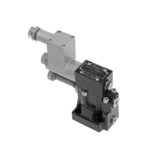
The G.DBW series pilot-operated explosion-proof pressure relief hydraulic valve is a cutting-edge hydraulic component specifically designed for applications in hazardous environments. With its exceptional explosion-proof features and reliable pressure relief capabilities, this valve ensures the utmost safety and performance in critical hydraulic systems.
The G.DBW series pilot-operated explosion-proof pressure relief hydraulic valve is the ultimate solution for ensuring safety and reliability in hazardous environments. With its explosion-proof design, reliable pressure relief capabilities, precise pressure control, and versatility, this valve delivers exceptional performance and protection in critical hydraulic systems; by following the recommended usage methods and maintenance practices, the G.DBW series valve guarantees longevity, safety, and optimal functionality. Upgrade your hydraulic system with the G.DBW series pilot-operated explosion-proof pressure relief hydraulic valve and experience unparalleled safety and reliability in hazardous environments.
G.DBW Series Pilot Operated Explosion-proof Pressure Relief Hydraulic Valve Key Characteristics:
- Räjähdyssuojattu rakenne:
- The G.DBW series valve is engineered with an explosion-proof design, making it suitable for use in environments where flammable gases or vapors are present.
- It meets rigorous safety standards and complies with industry regulations, reducing the risk of ignition or explosion in hazardous areas.
- Reliable Pressure Relief:
- This valve offers reliable pressure relief capabilities, protecting hydraulic systems from excessive pressure buildup.
- It automatically opens when the system pressure exceeds the set limit, diverting excess fluid to a low-pressure outlet and preventing potential damage or failures.
- Tarkka paineensäätö:
- The G.DBW series valve provides precise pressure control, allowing operators to set desired pressure levels within hydraulic systems.
- This feature ensures optimal system performance, protecting sensitive components and enhancing efficiency.
- Versatility and Customization:
- The valve is available in various sizes, pressure ratings, and configurations, accommodating various system requirements.
- It offers customization options for specific hydraulic applications, providing flexibility and adaptability.
G.DBW Series Pilot Operated Explosion-proof Pressure Relief Hydraulic Valve Parameter:
| Asennusasento | Valinnainen | ||||||
| Paino | G…DBW…10 | G…DBW…15 | G…DBW…20 | G…DBW…25 | G…DBW…30 | ||
| Base sub-plate mounting G…DBW | kg | about 5.6 | – | about 6.5 | – | about 7.9 | |
| threaded connection G…DBW..G.. | kg | about 7.9 | about 7.8 | about 7.7 | about 8.5 | about 8.4 | |
| Switching shock damping | kg | noin 0,6 | |||||
| Technical parameters of directional valve | Refer to the solenoid valvetype G…WE6,normally close use G…3WE6A9, normally open use G…3WE6B9 | ||||||
| Neste | Mineraaliöljy, joka sopii NBR- ja FKM-tiivisteille | ||||||
| Fosfaattiesteri FKM-tiivisteelle | |||||||
| Nesteen lämpötila-alue | ℃ | -30 - +80 (NBR-tiiviste) | |||||
| -20 - +80 (FKM-tiiviste) | |||||||
| Viskositeettialue | mm2/s | 10–800 | |||||
| Saastumisaste | Suurin sallittu nesteen kontaminaatioaste: Luokka 9. NAS 1638 tai 20/18/15, ISO4406 | ||||||
| Maks. käyttöpaine | Port A, B, X, P | baari | 350 | ||||
| Port Y or T DBW | baari | 210 | |||||
| Suurin asetuspaine | baari | 50; 100; 200; 315; 350 | |||||
| Min. | baari | Interrelated with Q(Refer to the characteristic curve) | |||||
| NS (NG) | 10 | 15 | 20 | 25 | 30 | ||
| Maks. virtausnopeus | Base Sub-plate mounting | L/min | 250 | – | 500 | – | 650 |
| threaded connection | L/min | 250 | 500 | 500 | 500 | 650 | |
G.DBW Series Pilot Operated Explosion-proof Pressure Relief Hydraulic Valve Advantages:
• Käytetään pohjalevyn asennukseen
• Installation face follow DIN 24340 E and ISO 6264
• Used in screw connection, Used for bottom sub-plate mounting
• Viisi painealuetta
• Unloading operation via a built-on solenoid directional valv
• Kaksi säätötyyppiä: nuppi, säätöruuvi suojakorkilla
• Optional switching shock damping
Usage Method Of G.DBW Series Pilot Operated Explosion-proof Pressure Relief Hydraulic Valve:
- Hazardous Environment Evaluation:
- Conduct a thorough evaluation of the hydraulic system’s operating environment to determine if it falls under hazardous classifications.
- Consider factors such as flammable gases, vapors, or combustible dust.
- Compliance and Certification:
- Ensure that the G.DBW series valve meets the necessary explosion-proof and safety standards for the specific hazardous environment.
- Verify compliance with regulatory bodies and obtain the appropriate certifications.
- Venttiilin valinta:
- Select the appropriate variant of the G.DBW series valve based on system specifications, including pressure requirements and flow capacity.
- Consider factors such as compatibility with other system components and the desired pressure relief setting.
- Asennus:
- Follow the manufacturer’s instructions for properly installing the G.DBW series valve in the hydraulic system.
- Ensure secure connections, proper grounding, and adherence to safety guidelines.
How Does A Hydraulic Spool Valve Work?
A hydraulic valve is a crucial component in hydraulic systems that controls the flow and direction of hydraulic fluid. It is responsible for regulating the pressure, allowing fluid to pass through, and directing it to various actuators or hydraulic components. The working principle of a hydraulic valve can be summarized as follows:
- Venttiilin rakenne:
- A hydraulic valve consists of a valve body, which houses the internal components, and a movable valve element, such as a spool or poppet.
- The valve body contains ports, passages, and chambers facilitating fluid flow.
- Fluid Flow Control:
- When hydraulic fluid enters the valve through the inlet port, it encounters the valve element, determining the flow path.
- The valve element can be moved manually, mechanically, or through hydraulic pressure.
- Venttiilien asennot:
- Hydraulic valves have different positions, including open, closed, and partially open, which control the fluid flow.
- In the closed position, the valve blocks the flow of fluid entirely.
- In the open position, the valve allows fluid to flow freely through the specified ports.
- In the partially open position, the valve restricts or controls the flow rate of the fluid.
- Spool Valve Operation:
- In a spool valve, a cylindrical spool with lands or channels controls the fluid flow.
- By moving the spool within the valve body, different lands align with specific ports, enabling or blocking fluid flow.
- The movement of the spool is typically achieved using mechanical linkage, solenoids, or hydraulic pressure acting on the spool.
- Poppet Valve Operation:
- In a poppet valve, a movable poppet or disc seals or unseals the fluid flow passage.
- When the poppet is in the closed position, it rests against a seat, blocking fluid flow.
- To open the valve, the poppet is moved away from the seat, allowing fluid to flow through the passage.
- Ohjausmekanismit:
- Hydraulic valves can be operated manually, mechanically, or through electrical means.
- Manual control involves levers, knobs, or handles to position the valve element manually.
- Mechanical control utilizes mechanical linkages or actuators to move the valve element.
- Electrical control employs solenoids or other electrically controlled devices to shift the valve element.
- Actuator Control:
- Hydraulic valves direct fluid to various hydraulic actuators, such as cylinders or motors.
- By opening or closing the appropriate valve ports, the hydraulic system can control the movement and operation of the actuators.
- System Stability and Safety:
- Hydraulic valves play a vital role in maintaining system stability and safety.
- Pressure relief valves, for example, protect the system from overpressure by diverting excess fluid to a low-pressure outlet.
Tehtaan kapasiteetti ja kapasiteetti:
(1) Kokoonpano
Meillä on ensiluokkainen riippumaton tutkimus- ja kehitystyön kokoonpanoalusta. Hydraulisylinterien tuotantopajassa on neljä puoliautomaattista nostosylinterin kokoonpanolinjaa ja yksi automaattinen kallistussylinterin kokoonpanolinja, joiden suunniteltu vuotuinen tuotantokapasiteetti on 1 miljoona kappaletta. Erikoissylinterin työpaja on varustettu erilaisilla eritelmillä puoliautomaattisen puhdistusasennuksen kokoonpanojärjestelmällä, jonka suunniteltu vuotuinen tuotantokapasiteetti on 200 000, ja se on varustettu kuuluisilla CNC-työstölaitteilla, työstökeskuksella, korkean tarkkuuden sylinterin käsittelyyn tarkoitetuilla erityislaitteilla, robottihitsauskoneella, automaattisella puhdistuslaitteella, automaattisella sylinterin kokoonpanokoneella ja automaattisella maalaustuotantolinjalla. Olemassa olevat kriittiset laitteet yli 300 sarjaa (sarjaa). Laiteresurssien optimaalinen kohdentaminen ja tehokas käyttö varmistavat tuotteiden tarkkuusvaatimukset ja täyttävät tuotteiden laatuvaatimukset.


(2) Koneistus
Työstöpaja on varustettu räätälöidyllä kaltevalla kiskosorvauskeskuksella, työstökeskuksella, suurnopeus-hiontakoneella, hitsausrobotilla ja muilla vastaavilla laitteilla, joilla voidaan käsitellä sylinteriputkia, joiden sisähalkaisija on enintään 400 mm ja enimmäispituus on 6 metriä.

(3) Hitsaus

(4) Maalaus ja pinnoitus
Pienillä ja keskisuurilla sylinterin automaattisilla vesipohjaisilla maalipinnoituslinjoilla automaattisen robotin lastaus- ja purku- ja automaattisen ruiskutuksen saavuttamiseksi, suunnittelukapasiteetti on 4000 kappaletta vuorossa;
Meillä on myös puoliautomaattinen maalauslinja suurille sylintereille, joka toimii voimaketjulla ja jonka suunnittelukapasiteetti on 60 laatikkoa työvuorossa.


(5) Testaus
Meillä on ensiluokkaiset tarkastustilat ja testialustat, joilla varmistetaan, että sylinterin suorituskyky täyttää vaatimukset.

Olemme yksi parhaista hydraulisylintereiden valmistajista. Voimme tarjota kattavia hydraulisylintereitä. Tarjoamme myös vastaavia maatalousvaihteistotOlemme vieneet tuotteitamme asiakkaille maailmanlaajuisesti ja ansainneet hyvän maineen erinomaisen tuotelaadun ja huoltopalvelumme ansiosta. Toivotamme tervetulleeksi asiakkaat kotimaassa ja ulkomailla ottamaan meihin yhteyttä neuvotellakseen liiketoimista, vaihtaakseen tietoja ja tehdä yhteistyötä kanssamme!