L-LC-sarjan paineensäätötoiminto hydraulinen venttiili
Yhtenä hydraulisylinterien valmistajista, toimittajista ja mekaanisten tuotteiden viejistä tarjoamme hydraulisylintereitä ja monia muita tuotteita.
Ota yhteyttä meihin saadaksesi lisätietoja.
Posti:sales@hydraulic-cylinders.net
Valmistaja toimittaja viejä hydraulisylinterit.
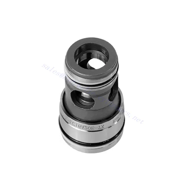
L-LC-sarjan paineensäätötoiminto hydraulinen venttiili
L-LC-sarjan paineensäätöhydrauliikkaventtiili on poikkeuksellinen hydrauliikkakomponentti, joka on suunniteltu tarjoamaan tarkkaa paineensäätöä erilaisissa sovelluksissa. Edistyksellisten ominaisuuksiensa ja kestävän rakenteensa ansiosta tämä venttiili antaa hydraulijärjestelmille optimaalisen suorituskyvyn ja tehokkuuden.
L-LC-sarjan paineensäätöhydrauliikkaventtiili mullistaa hydrauliikkajärjestelmät tarjoamalla tarkan paineensäädön, monipuolisuuden ja kestävyyden. Noudattamalla suositeltuja käyttömenetelmiä ja huolto-ohjeita voit hyödyntää L-LC-sarjan venttiilin täyden potentiaalin ja kokea paremman hallinnan, turvallisuuden ja tehokkuuden hydraulisissa sovelluksissasi. Päivitä hydrauliikkajärjestelmäsi jo tänään ja hyödynnä tarkkuuden ja hallinnan edut L-LC-sarjan paineensäätöhydrauliikkaventtiilillä.
L-LC-sarjan paineensäätötoiminto Hydraulisen venttiilin keskeiset ominaisuudet:
- Paineensäätötoiminto:
- L-LC-sarjan venttiilissä on kehittynyt paineensäätötoiminto, joka mahdollistaa tarkan hydraulisen paineen säädön järjestelmässä.
- Tämä ominaisuus varmistaa tasaisen ja luotettavan paineenhallinnan, mikä parantaa järjestelmän suorituskykyä, parantaa turvallisuutta ja vähentää energiankulutusta.
- Monipuoliset kokoonpanovaihtoehdot:
- Tämä venttiili on saatavana useissa eri kokoonpanoissa, mukaan lukien 2-tie- ja 3-tievaihtoehdot, mikä varmistaa yhteensopivuuden erilaisten hydrauliikkajärjestelmien vaatimusten kanssa.
- Kaksitiekonfiguraatio helpottaa paineen säätöä päälle/pois, kun taas kolmitierakenne mahdollistaa monimutkaisempia säätötoimintoja, kuten paineenalennusta tai ohitusta.
- Korkealaatuinen rakenne:
- L-LC-sarjan venttiili on huolellisesti suunniteltu korkealaatuisista materiaaleista ja tarkoilla valmistustekniikoilla kestävyyden ja pitkäikäisyyden varmistamiseksi.
- Sen kestävä rakenne kestää vaativia käyttöolosuhteita, kuten korkeita paineita, lämpötilan vaihteluita ja altistumista epäpuhtauksille.
- Nopea vasteaika:
- Tällä venttiilillä on vaikuttava vasteaika, joka mahdollistaa nopeat säädöt hydraulijärjestelmän paineenmuutoksiin.
- Nopea vasteaika varmistaa nopean ja tarkan ohjauksen, optimoi järjestelmän suorituskyvyn ja minimoi painevaihteluiden riskin.
L-LC-sarjan paineensäätötoiminto Hydraulinen venttiiliparametri:
| Tekniset tiedot | ||||||||
| Neste | Mineraaliöljy, joka sopii NBR- ja FKM-tiivisteille | |||||||
| Fosfaattiesteri FKM-tiivisteelle | ||||||||
| Nesteen lämpötila-alue | ℃ | -30 - +80 (NBR-tiiviste) | ||||||
| -20 - +80 (FKM-tiiviste) | ||||||||
| Viskositeettialue | mm2/s | 2,8–380 | ||||||
| Saastumisaste | Suurin sallittu nesteen kontaminaatioaste: Luokka 9. NAS 1638 tai 20/18/15, ISO4406 | |||||||
| Kaksitieiset patruunaventtiilit | ||||||||
| Suurin käyttöpaine - Portit A ja B | baari | 420 | ||||||
| Maks. virtausnopeus (suositus) | Koko | 16 | 25 | 32 | 40 | 50 | 63 | |
| Lautasventtiilin patruunat ”E” ja ”A” | L/min | 300 | 450 | 600 | 1000 | 1600 | 2500 | |
| Luistiventtiilin patruunat “D” ja “B” | L/min | 175 | 300 | 450 | 700 | 1400 | 1750 | |
L-LC-sarjan paineensäätötoiminto Hydraulisen venttiilin edut:
• Valinnainen paineensäätökansi ja muiden toimintojen integrointi
• Saatavilla on useita painetasoja
L-LC-sarjan paineensäätötoiminnon hydrauliventtiilin käyttötapa:
- Järjestelmän arviointi:
- Arvioi hydrauliikkajärjestelmäsi ja määritä erityiset paineensäätövaatimukset.
- Määritä, sopiiko L-LC-sarjan venttiili järjestelmääsi painealueen, virtausnopeuksien ja sovelluksesi yhteensopivuuden perusteella.
- Venttiilin valinta:
- Valitse L-LC-sarjan venttiilin sopiva versio järjestelmäparametrien ja paineensäätötarpeiden perusteella.
- Ota huomioon paineluokitus, virtauskapasiteetti, vasteaika ja yhteensopivuus tietyn sovelluksesi kanssa.
- Asennus:
- Noudata valmistajan asennusohjeita huolellisesti varmistaaksesi oikean kohdistuksen ja venttiilin turvallisen asennuksen.
- Käytä yhteensopivia hydrauliliittimiä, sovittimia ja tiivisteitä vuotamattomien liitosten muodostamiseksi. Kiristä liitokset riittävästi välttäen ylikiristämistä, joka voi vahingoittaa venttiiliä tai liittimiä.
- Paineen kalibrointi:
- Kalibroi L-LC-sarjan venttiili halutulle painealueelle käyttämällä sopivia paineenmittauslaitteita ja säätömekanismeja.
- Noudata valmistajan ohjeita paineen kalibrointimenetelmistä ja varmista, että venttiili toimii määriteltyjen painerajojen sisällä.
Kuinka asentaa hydraulinen virtauksen säätöventtiili?
Asenna hydraulinen virtauksen säätöventtiili noudattamalla näitä vaiheittaisia ohjeita:
- Tunnista venttiili: Määritä käyttämäsi hydraulisen virtauksen säätöventtiilin tyyppi. Saatavilla on erilaisia tyyppejä, kuten neulaventtiilejä, kuristinventtiilejä ja säädettäviä virtauksen säätöventtiilejä. Varmista, että venttiili sopii sovellukseesi ja on yhteensopiva hydraulijärjestelmäsi kanssa.
- Kerää tarvittavat työkalut ja materiaalit: Kerää tarvittavat työkalut ja materiaalit, mukaan lukien sopivat hydrauliliittimet, adapterit, letkut, jakoavaimet ja teflonteippi (kierteiden tiivistysaine). Katso valmistajan ohjeet tarvittavien työkalujen tai komponenttien osalta.
- Valmistele hydrauliikkajärjestelmä: Sammuta hydraulijärjestelmä ja vapauta paine aktivoimalla paineenalennusventtiili tai vetämällä hydraulisylintereitä sisään. Tämä vaihe on ratkaisevan tärkeä turvallisuuden kannalta ja estää tahattoman liikkeen tai hydraulinesteen vuotamisen.
- Virtaussuunnan tunnistaminen: Määritä hydraulijärjestelmän virtaussuunta. Yleensä virtaussuunta on merkitty hydrauliikkakomponenttien nuolilla. Varmista, että ymmärrät oikean virtaussuunnan ennen kuin jatkat.
- Määritä asennuspiste: Määritä hydrauliikkajärjestelmän hydrauliikkaventtiilin optimaalinen asennuspaikka. Ota huomioon tekijät, kuten saavutettavuus, toimilaitteen tai hydraulikomponentin läheisyys ja helppokäyttöisyys. Varmista, että venttiilin turvalliseen asennukseen on riittävästi tilaa.
- Asenna venttiili: Kiinnitä hydraulinen virtauksen säätöventtiili tukevasti valittuun paikkaan käyttämällä sopivia kiinnikkeitä tai puristimia. Varmista, että venttiili on oikeassa asennossa ja että tulo- ja lähtöaukot ovat kohdistettu virtaussuuntaan. Noudata valmistajan ohjeita venttiilisi erityisten asennusvaatimusten osalta.
- Yhdistä tulo- ja lähtöportit: Kiinnitä hydrauliletkut tai -putket hydraulivirtauksen säätöventtiilin tulo- ja lähtöportteihin. Käytä sopivia hydrauliliittimiä ja sovittimia vuotamattoman liitoksen luomiseksi. Levitä teflonteippiä tai kierretiivistettä liittimien uroskierteisiin varmistaaksesi turvallisen ja tiiviin liitoksen. Kiristä liitokset avaimilla vuotojen välttämiseksi, mutta varo kiristämästä liikaa.
- Säädä virtausnopeutta: Virtaussäätöventtiilin tyypistä riippuen virtausnopeutta voi olla tarpeen säätää. Joissakin venttiileissä on säädettävät nupit tai ruuvit, joiden avulla virtausnopeutta voidaan hienosäätää. Aseta haluttu virtausnopeus valmistajan ohjeiden mukaisesti.
- Testaa järjestelmä: Kun hydraulinen virtauksen säätöventtiili on asennettu, palauta hydraulijärjestelmän paine hitaasti. Testaa järjestelmä varmistaaksesi, että venttiili toimii oikein. Tarkkaile virtausnopeutta ja varmista, että venttiili ohjaa virtausta tarkoitetulla tavalla. Tee tarvittavat säädöt halutun virtausnopeuden saavuttamiseksi.
- Seuranta ja ylläpito: Tarkasta säännöllisesti hydraulinen virtauksen säätöventtiili vuotojen, vaurioiden tai heikentyneen suorituskyvyn varalta. Puhdista venttiili ja sitä ympäröivä alue liasta ja roskista, jotka voivat vaikuttaa sen toimintaan. Noudata valmistajan suosittelemaa huolto-ohjelmaa ja -ohjeita optimaalisen suorituskyvyn ja pitkän käyttöiän varmistamiseksi.
Tehtaan kapasiteetti ja kapasiteetti:
(1) Kokoonpano
Meillä on ensiluokkainen riippumaton tutkimus- ja kehitystyön kokoonpanoalusta. Hydraulisylinterien tuotantopajassa on neljä puoliautomaattista nostosylinterin kokoonpanolinjaa ja yksi automaattinen kallistussylinterin kokoonpanolinja, joiden suunniteltu vuotuinen tuotantokapasiteetti on 1 miljoona kappaletta. Erikoissylinterin työpaja on varustettu erilaisilla eritelmillä puoliautomaattisen puhdistusasennuksen kokoonpanojärjestelmällä, jonka suunniteltu vuotuinen tuotantokapasiteetti on 200 000, ja se on varustettu kuuluisilla CNC-työstölaitteilla, työstökeskuksella, korkean tarkkuuden sylinterin käsittelyyn tarkoitetuilla erityislaitteilla, robottihitsauskoneella, automaattisella puhdistuslaitteella, automaattisella sylinterin kokoonpanokoneella ja automaattisella maalaustuotantolinjalla. Olemassa olevat kriittiset laitteet yli 300 sarjaa (sarjaa). Laiteresurssien optimaalinen kohdentaminen ja tehokas käyttö varmistavat tuotteiden tarkkuusvaatimukset ja täyttävät tuotteiden laatuvaatimukset.


(2) Koneistus
Työstöpaja on varustettu räätälöidyllä kaltevalla kiskosorvauskeskuksella, työstökeskuksella, suurnopeus-hiontakoneella, hitsausrobotilla ja muilla vastaavilla laitteilla, joilla voidaan käsitellä sylinteriputkia, joiden sisähalkaisija on enintään 400 mm ja enimmäispituus on 6 metriä.

(3) Hitsaus

(4) Maalaus ja pinnoitus
Pienillä ja keskisuurilla sylinterin automaattisilla vesipohjaisilla maalipinnoituslinjoilla automaattisen robotin lastaus- ja purku- ja automaattisen ruiskutuksen saavuttamiseksi, suunnittelukapasiteetti on 4000 kappaletta vuorossa;
Meillä on myös puoliautomaattinen maalauslinja suurille sylintereille, joka toimii voimaketjulla ja jonka suunnittelukapasiteetti on 60 laatikkoa työvuorossa.


(5) Testaus
Meillä on ensiluokkaiset tarkastustilat ja testialustat, joilla varmistetaan, että sylinterin suorituskyky täyttää vaatimukset.

Olemme yksi parhaista hydraulisylintereiden valmistajista. Voimme tarjota kattavia hydraulisylintereitä. Tarjoamme myös vastaavia maatalousvaihteistotOlemme vieneet tuotteitamme asiakkaille maailmanlaajuisesti ja ansainneet hyvän maineen erinomaisen tuotelaadun ja huoltopalvelumme ansiosta. Toivotamme tervetulleeksi asiakkaat kotimaassa ja ulkomailla ottamaan meihin yhteyttä neuvotellakseen liiketoimista, vaihtaakseen tietoja ja tehdä yhteistyötä kanssamme!
Hydraulisylinteri Sovellus:
