M-SED Series Directional Poppet Hydraulic Valve With Solenoid Actuation
Yhtenä hydraulisylinterien valmistajista, toimittajista ja mekaanisten tuotteiden viejistä tarjoamme hydraulisylintereitä ja monia muita tuotteita.
Ota yhteyttä meihin saadaksesi lisätietoja.
Posti:sales@hydraulic-cylinders.net
Valmistaja toimittaja viejä hydraulisylinterit.
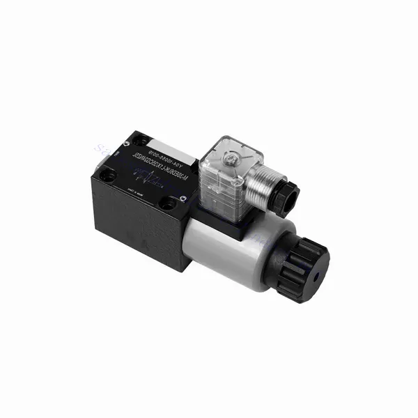
M-SED Series Directional Poppet Hydraulic Valve With Solenoid Actuation
The M-SED series directional poppet hydraulic valve with solenoid actuation is a cutting-edge solution that provides precise control and optimal efficiency in hydraulic systems. With its innovative design, reliable performance, and advanced solenoid actuation, this valve offers enhanced fluid flow control, flexibility, and compatibility with various industrial applications.
The M-SED series directional poppet hydraulic valve with solenoid actuation is a reliable and efficient solution for hydraulic systems. With its directional poppet design, advanced solenoid actuation, versatility, and high flow capacity, this valve offers precise control, enhanced efficiency, and compatibility with various applications. The M-SED series valve delivers optimal performance and reliability by following the recommended usage methods and adhering to regular maintenance practices. Upgrade your hydraulic system with the M-SED series directional poppet hydraulic valve and experience enhanced control, efficiency, and productivity.
M-SED Series Directional Poppet Hydraulic Valve With Solenoid Actuation Key Characteristics:
- Suunnattu lautasventtiilin suunnittelu:
- The M-SED series valve features a directional poppet design, ensuring reliable and efficient fluid flow control.
- Se mahdollistaa nopeat vasteajat ja nesteen suunnan tarkan säätelyn, mikä parantaa järjestelmän kokonaissuorituskykyä.
- Solenoidin käyttö:
- This hydraulic valve is equipped with advanced solenoid actuation and provides remote and automated control capabilities.
- Solenoidi mahdollistaa nopean ja tarkan vaihdon eri virtausreittien välillä, mikä parantaa toiminnan tehokkuutta.
- Monipuolisuus ja yhteensopivuus:
- The M-SED series valve is highly versatile and compatible with various hydraulic systems and applications.
- Se voidaan integroida saumattomasti teollisuuskoneisiin, mobiililaitteisiin ja automaatiojärjestelmiin, mikä parantaa suorituskykyä.
- Suuri virtauskapasiteetti:
- With its robust design and optimized flow paths, the M-SED series valve offers high flow capacity.
- Se varmistaa tehokkaan nesteensiirron, vähentää painehäviöitä ja maksimoi järjestelmän läpimenon.
M-SED Series Directional Poppet Hydraulic Valve With Solenoid Actuation Parameter:
| Tekniset tiedot | NG6 | NG10 | ||
| Asennusasento | Valinnainen | |||
| Ympäristön lämpötila | ℃ | -30 - +50 (NBR-tiivisteet) | ||
| -20 - +50 (FKM-tiivisteet) | ||||
| Paino | Kaksi kolmitieinen solenoidisuuntaventtiili | Kg | 1.5 | 2.6 |
| Kaksi nelitieistä solenoidisuuntaventtiiliä | Kg | 2.3 | 3.9 | |
| Maks. käyttöpaine | baari | 350 | 350 | |
| Maks. virtausnopeus | L/min | 25 | 40 | |
| Neste | Mineraaliöljy, joka sopii NBR- ja FKM-tiivisteille | |||
| Fosfaattiesteri FKM-tiivisteelle | ||||
| Nesteen lämpötila-alue | ℃ | -30 - +80 (NBR-tiivisteet) | ||
| -20 - +80 (FKM-tiivisteet) | ||||
| Viskositeettialue | mm2/s | 2,8–500 | ||
| Saastumisaste | Maximum permissible degree of fluid contamination: Class 9. NAS 1638 | Suurin sallittu nesteen kontaminaatioaste: Luokka 9. NAS 1638 tai 20/18/15, ISO4406 | ||
M-SED Series Directional Poppet Hydraulic Valve With Solenoid Actuation Advantages:
• Suora solenoidisulkuventtiili
• Asennuspinta standardien DIN 24340 A, ISO 4401 ja CETOP-RP 121H mukaisesti
• Ei vuotoa
• Reagoiva kytkentä korkeassa paineessa
• Replacing the coil does not require opening the sealed chamber
• Solenoidikäämi voi pyöriä 90°
• With manual emergency control optional
Usage Method Of M-SED Series Directional Poppet Hydraulic Valve With Solenoid Actuation:
- Järjestelmän arviointi:
- Suorita hydraulijärjestelmän perusteellinen arviointi määrittääksesi erityisvaatimukset ja käyttöparametrit.
- Consider factors such as flow rates, pressure ratings, and compatibility with the M-SED Series Valve.
- Venttiilin valinta:
- Select the appropriate M-SED Series Valve variant based on the system requirements and specifications.
- Consider factors such as port size, voltage compatibility, and solenoid actuation parameters.
- Asennus:
- Follow the manufacturer’s instructions for proper installation of the M-SED Series Valve in the hydraulic system.
- Varmista tukeva kiinnitys, oikea kohdistus ja asianmukainen tiivistys vuotojen estämiseksi ja optimaalisen suorituskyvyn varmistamiseksi.
- Sähköliitännät:
- Kytke solenoidin käyttöjohdot sopivaan virtalähteeseen suositeltujen johdotusohjeiden mukaisesti.
- Varmista oikea napaisuus ja eristys sähköhäiriöiden tai turvallisuusriskien välttämiseksi.
How Does A Hydraulic Counterbalance Valve Work?
A hydraulic counterbalance valve is a type of valve used in hydraulic systems to control the motion and stability of loads. It is commonly employed in applications where there is a need to control the descent or lowering of heavy loads, such as in cranes, excavators, and material handling equipment. The primary function of a counterbalance valve is to provide controlled resistance to the downward movement of a load, preventing it from free-falling or dropping uncontrollably.
Here’s how a hydraulic counterbalance valve works:
- Flow Control:
- When the load is lifted, hydraulic fluid flows from the pump to the cylinder, raising the load.
- The counterbalance valve is installed in the line between the cylinder and the directional control valve.
- Check Valve Function:
- The counterbalance valve incorporates a built-in check valve that allows the free flow of oil from the pump to the cylinder during the lifting phase.
- The check valve opens, permitting fluid flow in one direction while blocking it in the opposite direction.
- Counterbalance Function:
- When the lifting action is complete and the directional control valve is shifted to the neutral position, the counterbalance valve comes into play.
- As the load starts to descend, the pressure at the cylinder port of the counterbalance valve increases.
- Pilot Pressure:
- The increased pressure at the cylinder port acts on a pilot piston within the counterbalance valve.
- This pilot pressure opposes the spring force in the valve, causing the valve to open gradually.
- Flow Restriction:
- As the counterbalance valve opens, it creates a restricted flow path for the hydraulic fluid returning from the cylinder.
- This restriction slows down the rate of fluid flow, providing controlled resistance against the load’s downward motion.
- Load Control:
- The counterbalance valve modulates the flow restriction based on the load’s weight and the desired speed of descent.
- By adjusting the spring tension or using adjustable counterbalance valves, the valve’s setting can be customized for specific applications.
- Stability and Safety:
- The counterbalance valve ensures stability and safety by preventing the load from dropping too quickly or causing uncontrolled movements.
- It maintains the load in a stable position, even when external forces or variations in the hydraulic system occur.
Tehtaan kapasiteetti ja kapasiteetti:
(1) Kokoonpano
Meillä on ensiluokkainen riippumaton tutkimus- ja kehitystyön kokoonpanoalusta. Hydraulisylinterien tuotantopajassa on neljä puoliautomaattista nostosylinterin kokoonpanolinjaa ja yksi automaattinen kallistussylinterin kokoonpanolinja, joiden suunniteltu vuotuinen tuotantokapasiteetti on 1 miljoona kappaletta. Erikoissylinterin työpaja on varustettu erilaisilla eritelmillä puoliautomaattisen puhdistusasennuksen kokoonpanojärjestelmällä, jonka suunniteltu vuotuinen tuotantokapasiteetti on 200 000, ja se on varustettu kuuluisilla CNC-työstölaitteilla, työstökeskuksella, korkean tarkkuuden sylinterin käsittelyyn tarkoitetuilla erityislaitteilla, robottihitsauskoneella, automaattisella puhdistuslaitteella, automaattisella sylinterin kokoonpanokoneella ja automaattisella maalaustuotantolinjalla. Olemassa olevat kriittiset laitteet yli 300 sarjaa (sarjaa). Laiteresurssien optimaalinen kohdentaminen ja tehokas käyttö varmistavat tuotteiden tarkkuusvaatimukset ja täyttävät tuotteiden laatuvaatimukset.


(2) Koneistus
Työstöpaja on varustettu räätälöidyllä kaltevalla kiskosorvauskeskuksella, työstökeskuksella, suurnopeus-hiontakoneella, hitsausrobotilla ja muilla vastaavilla laitteilla, joilla voidaan käsitellä sylinteriputkia, joiden sisähalkaisija on enintään 400 mm ja enimmäispituus on 6 metriä.

(3) Hitsaus

(4) Maalaus ja pinnoitus
Pienillä ja keskisuurilla sylinterin automaattisilla vesipohjaisilla maalipinnoituslinjoilla automaattisen robotin lastaus- ja purku- ja automaattisen ruiskutuksen saavuttamiseksi, suunnittelukapasiteetti on 4000 kappaletta vuorossa;
Meillä on myös puoliautomaattinen maalauslinja suurille sylintereille, joka toimii voimaketjulla ja jonka suunnittelukapasiteetti on 60 laatikkoa työvuorossa.


(5) Testaus
Meillä on ensiluokkaiset tarkastustilat ja testialustat, joilla varmistetaan, että sylinterin suorituskyky täyttää vaatimukset.

Olemme yksi parhaista hydraulisylintereiden valmistajista. Voimme tarjota kattavia hydraulisylintereitä. Tarjoamme myös vastaavia maatalousvaihteistotOlemme vieneet tuotteitamme asiakkaille maailmanlaajuisesti ja ansainneet hyvän maineen erinomaisen tuotelaadun ja huoltopalvelumme ansiosta. Toivotamme tervetulleeksi asiakkaat kotimaassa ja ulkomailla ottamaan meihin yhteyttä neuvotellakseen liiketoimista, vaihtaakseen tietoja ja tehdä yhteistyötä kanssamme!
Hydraulisylinteri Sovellus:
