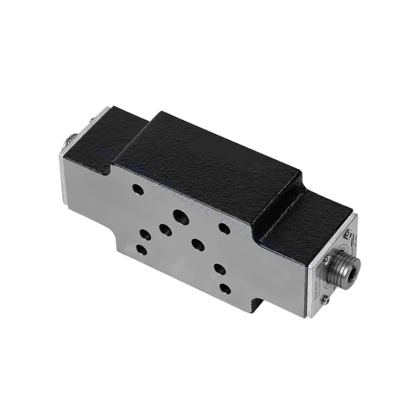
Z2FS-sarjan kaksoiskaasuventtiilin hydraulinen tarkistusventtiili
Yhtenä hydraulisylinterien valmistajista, toimittajista ja mekaanisten tuotteiden viejistä tarjoamme hydraulisylintereitä ja monia muita tuotteita.
Ota yhteyttä meihin saadaksesi lisätietoja.
Posti:sales@hydraulic-cylinders.net
Valmistaja toimittaja viejä hydraulisylinterit.
Z2FS-sarjan kaksoiskaasuventtiilin hydraulinen tarkistusventtiili
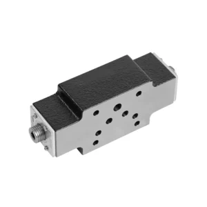
The Z2FS series double throttle check hydraulic valve is a powerful hydraulic component designed to provide exceptional control and reliability in hydraulic systems. With its unique double throttle check functionality, this valve offers versatility and enhanced performance, allowing operators to optimize their hydraulic applications.
The Z2FS series double throttle check hydraulic valve is an indispensable component for achieving precise control and reliability in hydraulic systems. With its unique double-throttle check design, this valve offers versatility, enhanced control, and system stability. By following the recommended usage methods and maintenance guidelines, operators can ensure the longevity, reliability, and optimal functionality of the Z2FS series double-throttle check hydraulic valve. Upgrade your hydraulic system with this exceptional valve and experience enhanced performance, versatility, and operational efficiency.
Z2FS Series Double Throttle Check Hydraulic Valve Key Characteristics:
- Double Throttle Check Design:
- The Z2FS series valve features a specialized double throttle check design, combining the functionalities of throttle and check valves in one unit.
- This design offers precise flow control and prevents reverse flow, ensuring optimal performance and system efficiency.
- Monipuolinen käyttö:
- The Z2FS series valve is suitable for various hydraulic systems and applications, including industrial machinery, construction equipment, and agricultural machinery.
- Its versatility allows for seamless integration into various hydraulic setups, providing reliable control and operation.
- Enhanced Control and Stability:
- With its double throttle check functionality, this valve offers precise control over flow rates, enabling operators to optimize the speed and position of hydraulic actuators.
- The valve’s ability to prevent reverse flow enhances system stability and reliability, protecting sensitive components from potential damage.
- Compact and Space-saving Design:
- The Z2FS series valve features a compact and space-saving design, making it ideal for applications with limited installation space.
- Its small footprint allows for flexible installation and easy integration into existing hydraulic systems.
Z2FS Series Double Throttle Check Hydraulic Valve Parameter:
| Tekniset tiedot | NG6 L4X type | NG6-22 type | ||||||
| Asennusasento | / | Valinnainen | ||||||
| Virtaussuunta | / | One direction throttle, return through the check valve by another direction | ||||||
| Neste | Mineraaliöljy, joka sopii NBR- ja FKM-tiivisteille | Mineraaliöljy, fosfaattiesteri | ||||||
| Fosfaattiesteri FKM-tiivisteelle | ||||||||
| Nesteen lämpötila-alue | ℃ | -30 to +80(NBR seals) | -20 to +80 | |||||
| -20 to +80(FKM seals) | ||||||||
| Viskositeettialue | mm2/s | 10–800 | ||||||
| Saastumisaste | Suurin sallittu nesteen kontaminaatioaste: Luokka 9. NAS 1638 tai 20/18/15, ISO4406 | |||||||
| Nominal flow | baari | 315 | / | |||||
| Maks. käyttöpaine | baari | / | to 350 | |||||
| Maks. virtausnopeus | L/min | 80 | / | |||||
| Koko | / | 6 | 10 | 16 | 22 | |||
| Paino | kg | about 1.0 | 0.9 | 3.1 | 4.7 | 8 | ||
Z2FS Series Double Throttle Check Hydraulic Valve Advantages:
NG6 L4X
• Sandwich-tyyppinen rakenne
• Asennuspinta standardien DIN 24340 A ja ISO 4401 mukaisesti
• Used to restrict the main flow or to control the flow of the two working oil orifices
• Used in inlet or outlet throttle
NG6-22 type
• Sandwich-tyyppinen rakenne
• Asennuspinta standardien DIN 24340 A ja ISO 4401 mukaisesti
• Used to limit the main port flow or pilot oil flow of two actuator ports
Usage Method Of Z2FS Series Double Throttle Check Hydraulic Valve :
- Järjestelmän arviointi:
- Begin by assessing the hydraulic system requirements, considering flow rates, pressure differentials, and system specifications.
- Determine if the double throttle check functionality of the Z2FS series valve is necessary for the specific application.
- Venttiilin valinta:
- Select the appropriate variant of the Z2FS series valve based on system parameters and flow control requirements.
- Ota huomioon esimerkiksi suurin virtausnopeus, paineluokitus ja yhteensopivuus muiden järjestelmäkomponenttien kanssa.
- Asennus:
- Follow the manufacturer’s installation instructions carefully, ensuring proper alignment and secure valve connections.
- Pay close attention to flow direction indicators, ensuring correct installation of fittings and seals.
- Flow Control Adjustment:
- Once installed, adjust the throttle control of the valve to achieve the desired flow rate.
- Käyttäjät voivat hienosäätää virtauksen säätöä hydraulisten toimilaitteiden erityisvaatimusten mukaan, mikä optimoi suorituskyvyn ja tarkkuuden.
How Hydraulic Valve Lifters Work?
Hydraulinen solenoidiventtiili on sähkömekaaninen laite, joka ohjaa hydraulinesteen virtausta järjestelmässä. Se toimii virransyöttöisen solenoidin periaatteella, joka luo magneettikentän venttiilimekanismin käyttämiseksi. Tässä on erittely siitä, miten hydraulinen solenoidiventtiili toimii:
- Venttiilin rakenne:
- Hydraulinen solenoidiventtiili koostuu tyypillisesti venttiilirungosta, solenoidikäämistä, männästä tai kelamekanismista ja useista nesteen virtausta varten tarkoitetuista porteista.
- Venttiilirunko sisältää virtauksen ohjaamiseen tarvittavat sisäiset komponentit ja nestekanavat.
- Solenoidikäämi ympäröi mäntää tai kelaa ja tuottaa magneettikentän, kun se saa virtaa.
- Normaalisti suljettu (NC) ja normaalisti avoin (NO) -tilat:
- Hydrauliset solenoidiventtiilit voidaan konfiguroida lepotilastaan riippuen joko normaalisti suljetuiksi (NC) tai normaalisti avoimiksi (NO).
- NC-konfiguraatiossa venttiili on jännitteettömänä suljettuna, mikä estää nesteen virtauksen.
- NO-konfiguraatiossa venttiili on auki jännitteettömänä, jolloin neste pääsee virtaamaan.
- Venttiilin käyttö:
- Kun solenoidikäämiin kohdistetaan sähkövirta, se synnyttää magneettikentän.
- Tämä magneettikenttä vetää puoleensa mäntää tai kelaa, jolloin se liikkuu jousta tai paine-eroa vasten venttiilin rakenteesta riippuen.
- Männän tai kelan liike avaa tai sulkee venttiiliportit, mikä ohjaa hydraulinesteen virtausta.
- Sähköinen ohjaus:
- Hydraulisen solenoidiventtiilin solenoidikäämiä ohjataan tyypillisesti sähköpiirillä, kuten kytkimellä tai ohjelmoitavalla logiikkaohjaimella (PLC).
- Kun virtapiiriin syötetään virtaa, se päästää virran kulkemaan solenoidikäämin läpi, mikä aktivoi venttiilin.
- Kun virtapiiri katkeaa, magneettikenttä häviää ja venttiili palaa lepotilaansa.
- Virtaussuunta ja paine:
- Hydraulisissa solenoidiventtiileissä on erilaiset porttikonfiguraatiot nesteen virtauksen suunnan ja paineen säätämiseksi.
- Venttiilin rakenteesta riippuen siinä voi olla imuaukot, poistoaukot ja pakoputket.
- Männän tai kelan asento määrittää, mitkä portit on kytketty, jolloin neste voi virrata tiettyihin suuntiin ja painetasot säätyvät.
- Sovellukset:
- Hydraulisia solenoidiventtiilejä käytetään laajalti eri teollisuudenaloilla ja sovelluksissa, joissa tarvitaan tarkkaa nestevirtauksen säätöä.
- Niitä löytyy teollisuuskoneiden, rakennuslaitteiden, maatalouskoneiden ja autoteollisuuden hydraulijärjestelmistä.
- Edut:
- Hydraulisilla solenoidiventtiileillä on useita etuja, kuten nopeat vasteajat, tarkka ohjaus, kompakti koko ja helppo integrointi hydraulijärjestelmiin.
- Niiden sähköinen ohjaus mahdollistaa automatisoinnin ja etäkäytön, mikä parantaa järjestelmän tehokkuutta ja käyttömukavuutta.
Tehtaan kapasiteetti ja kapasiteetti:
(1) Kokoonpano
Meillä on ensiluokkainen riippumaton tutkimus- ja kehitystyön kokoonpanoalusta. Hydraulisylinterien tuotantopajassa on neljä puoliautomaattista nostosylinterin kokoonpanolinjaa ja yksi automaattinen kallistussylinterin kokoonpanolinja, joiden suunniteltu vuotuinen tuotantokapasiteetti on 1 miljoona kappaletta. Erikoissylinterin työpaja on varustettu erilaisilla eritelmillä puoliautomaattisen puhdistusasennuksen kokoonpanojärjestelmällä, jonka suunniteltu vuotuinen tuotantokapasiteetti on 200 000, ja se on varustettu kuuluisilla CNC-työstölaitteilla, työstökeskuksella, korkean tarkkuuden sylinterin käsittelyyn tarkoitetuilla erityislaitteilla, robottihitsauskoneella, automaattisella puhdistuslaitteella, automaattisella sylinterin kokoonpanokoneella ja automaattisella maalaustuotantolinjalla. Olemassa olevat kriittiset laitteet yli 300 sarjaa (sarjaa). Laiteresurssien optimaalinen kohdentaminen ja tehokas käyttö varmistavat tuotteiden tarkkuusvaatimukset ja täyttävät tuotteiden laatuvaatimukset.


(2) Koneistus
Työstöpaja on varustettu räätälöidyllä kaltevalla kiskosorvauskeskuksella, työstökeskuksella, suurnopeus-hiontakoneella, hitsausrobotilla ja muilla vastaavilla laitteilla, joilla voidaan käsitellä sylinteriputkia, joiden sisähalkaisija on enintään 400 mm ja enimmäispituus on 6 metriä.

(3) Hitsaus

(4) Maalaus ja pinnoitus
Pienillä ja keskisuurilla sylinterin automaattisilla vesipohjaisilla maalipinnoituslinjoilla automaattisen robotin lastaus- ja purku- ja automaattisen ruiskutuksen saavuttamiseksi, suunnittelukapasiteetti on 4000 kappaletta vuorossa;
Meillä on myös puoliautomaattinen maalauslinja suurille sylintereille, joka toimii voimaketjulla ja jonka suunnittelukapasiteetti on 60 laatikkoa työvuorossa.


(5) Testaus
Meillä on ensiluokkaiset tarkastustilat ja testialustat, joilla varmistetaan, että sylinterin suorituskyky täyttää vaatimukset.

Olemme yksi parhaista hydraulisylintereiden valmistajista. Voimme tarjota kattavia hydraulisylintereitä. Tarjoamme myös vastaavia maatalousvaihteistotOlemme vieneet tuotteitamme asiakkaille maailmanlaajuisesti ja ansainneet hyvän maineen erinomaisen tuotelaadun ja huoltopalvelumme ansiosta. Toivotamme tervetulleeksi asiakkaat kotimaassa ja ulkomailla ottamaan meihin yhteyttä neuvotellakseen liiketoimista, vaihtaakseen tietoja ja tehdä yhteistyötä kanssamme!
Hydraulisylinteri Sovellus:
