DRE(E) Series Proportional Pressure Reducing Hydraulic Valve
DRE(E) Series Proportional Pressure Reducing Hydraulic Valve
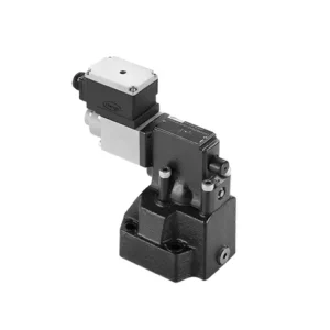
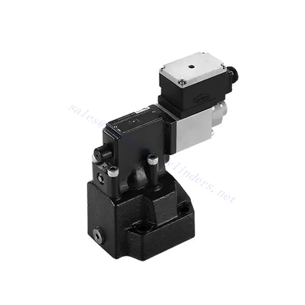
The DRE(E) series proportional pressure-reducing hydraulic valve is a cutting-edge hydraulic component that provides precise pressure control in hydraulic systems. With its advanced proportional control technology, this valve ensures optimal performance, efficiency, and safety.
The DRE(E) series proportional pressure-reducing hydraulic valve empowers hydraulic systems with precise pressure control, enhanced efficiency, and equipment protection. With its advanced proportional control technology, this valve ensures optimal performance across various applications. By following the recommended usage methods and maintenance guidelines, you can maximize the benefits and reliability of the DRE(E) series valve, elevating the pressure control and overall performance of your hydraulic system. Upgrade your hydraulic setup today and experience superior pressure regulation with the DRE(E) series proportional pressure-reducing hydraulic valve.
DRE(E) Series Proportional Pressure Reducing Hydraulic Valve Key Characteristics:
- Proportional Pressure Reduction:
- The DRE(E) series valve offers precise and proportional pressure reduction, enabling dynamic hydraulic pressure control.
- It ensures accurate pressure regulation, maintaining a consistent and safe pressure level within the hydraulic system.
- Amélioration de l'efficacité du système :
- Cette vanne permet un contrôle précis de la pression hydraulique, ce qui améliore l'efficacité du système et réduit la consommation d'énergie.
- By maintaining the desired pressure levels, it minimizes pressure fluctuations, optimizes system performance, and lowers operational costs.
- Sécurité et protection des équipements :
- The DRE(E) series valve acts as a protective mechanism by limiting the pressure within the hydraulic system, safeguarding equipment and operators.
- Il empêche une accumulation excessive de pression, réduisant ainsi le risque d'endommagement des composants, de défaillances du système et d'accidents potentiels.
- Fonctionnalité de contrôle proportionnel :
- With its proportional control technology, the DRE(E) series valve offers smooth and precise pressure adjustment.
- Il permet un contrôle de la pression en temps réel, assurant une intégration transparente dans divers systèmes et applications hydrauliques.
DRE(E) Series Proportional Pressure Reducing Hydraulic Valve Parameter:
| Général | ||||
| Fluide | Huile minérale adaptée aux joints NBR et FKM | |||
| Ester phosphate pour joint FKM | ||||
| Plage de température du fluide | °C | -30 à +80 (joints NBR) | ||
| -20 à +80 (scellés FKM) | ||||
| Plage de viscosité | mm2/s | 2,8 à 380 | ||
| Degré de contamination | Degré maximal admissible de contamination des fluides : Classe 9. NAS 1638 ou 20/18/15, ISO4406 | |||
| Pression de service max. | 315 bars | |||
| Port A, B, X | bar | 50; 100; 200; 315 | ||
| Pression de réglage maximale | bar | En ce qui concerne le débit (Q), voir les courbes caractéristiques. | ||
| Pression minimale réglable | = Pression minimale réglable | |||
| Pression minimale réglable à la valeur de commande 0 | Séparément et à pression nulle par rapport aux réservoirs | |||
| Orifice de retour de pression d'huile Y | bar | Réglage de la pression | Plage de pression sous pression de sécurité maximale | |
| Pression de sécurité maximale (réglable en continu) | 50 bars | 10-60+20 bar | ||
| 100 bars | 10-120+20 bar | |||
| 200 bars | 10-220+20 bar | |||
| 315 bars | 10-340+20 bar | |||
| Condition de réglage de sécurité de pression maximale | Lorsque la pression nominale est de 50 bars, entre 60 et 80 bars | |||
| Lorsque la pression nominale est de 100 bars, entre 120 et 140 bars | ||||
| Lorsque la pression nominale est de 200 bars, entre 220 et 240 bars | ||||
| Lorsque la pression nominale est de 315 bars, entre 340 et 360 bars | ||||
| Taille | 10 | 25 | 32 | |
| Débit max. | 200 | 400 | 600 | |
| Huile pilote (pour la vanne pilote) | L/min | 0,7 à 2 | ||
| Linéarité | L/min | ±3,5% | ||
| Répétabilité | <±2% | |||
| Hystérèse | avec des ondulations | sans frémissement | ||
| ±1,5% P max (200 Hz, amplitude 200 mAss) | ±4,5% P max | |||
| Temps de commutation | 30 à 150 ms (indépendant du système) | |||
| données électriques | ||||
| Pouvoir | DC | |||
| Courant minimal du solénoïde | mA | 100 | ||
| Courant maximal du solénoïde | mA | 800 | ||
| résistance de la bobine | 19,5 Ω à 20 °C, valeur maximale à chaud : 28,8 Ω | |||
| État de travail | Continu | |||
| Plage de température ambiante maximale | +50℃ | |||
| raccordement électrique | Connecteur enfichable DIN 43 650/2 +SL/PG11 | |||
| Isolation conforme à la norme DIN 40 050 | IP 65 | |||
| Amplificateur | VT2000 | |||
DRE(E) Series Proportional Pressure Reducing Hydraulic Valve Advantages:
• Utilisé pour le montage de la sous-plaque inférieure
• La face de montage est conforme aux normes DIN 24340 E et ISO 6264
• Utilisé dans l'installation du bloc de passage d'huile
• Quatre plages de pression
• Structure de protection contre la pression la plus élevée (en option)
• Amplificateur électronique compatible de type VT-2000 (à commander séparément)
Usage Method Of DRE(E) Series Proportional Pressure Reducing Hydraulic Valve:
- Évaluation du système :
- Évaluez votre système hydraulique et identifiez les exigences spécifiques en matière de contrôle de la pression.
- Determine if the DRE(E) series valve is compatible with your system based on its pressure range, flow capacity, and other specifications.
- Sélection de la vanne :
- Choose the appropriate DRE(E) series valve variant based on your system parameters, pressure range, and flow requirements.
- Tenir compte de la pression nominale maximale, du temps de réponse et des conditions de fonctionnement.
- Installation:
- Suivez attentivement les instructions d'installation du fabricant, en veillant à un alignement correct et à une fixation sécurisée de la vanne.
- Raccordez la vanne au système hydraulique en veillant à l'étanchéité des connexions et au bon alignement du sens d'écoulement.
- Réglage de la pression :
- Utilize the proportional control signal or adjustment mechanism provided with the DRE(E) series valve to set the desired pressure reduction level.
- Réglez la vanne par paliers, en surveillant les indications du manomètre et la réponse du système pour obtenir un contrôle précis de la pression.
Comment régler la soupape de décharge de pression hydraulique ?
Le réglage d'une soupape de décharge hydraulique permet de réguler la pression maximale au sein d'un système hydraulique. Ceci est essentiel pour préserver l'intégrité du système et éviter d'endommager ses composants. Voici un guide étape par étape pour régler une soupape de décharge hydraulique :
- Identifier la soupape de décharge de pression :
- Repérez la soupape de décharge de pression hydraulique dans votre système. Elle est généralement située sur la conduite hydraulique ou intégrée à un bloc collecteur.
- Comprendre la conception de la vanne :
- Familiarisez-vous avec la conception spécifique de la soupape de décharge de pression que vous utilisez. Différentes soupapes peuvent avoir des mécanismes de réglage variés, tels qu'un bouton, une vis ou un contre-écrou.
- Déterminer le réglage de pression souhaité :
- Évaluez les exigences de votre système hydraulique et déterminez la pression maximale souhaitée. Tenez compte des spécifications du système, des conditions de charge et des limites de sécurité.
- Préparer le système :
- Avant tout réglage, coupez le système hydraulique et relâchez la pression en déplaçant les leviers de commande d'avant en arrière ou en suivant la procédure recommandée par le fabricant.
- Localisez le mécanisme de réglage :
- Identifiez le mécanisme de réglage de la soupape de décharge de pression. Il peut s'agir d'un bouton, d'une vis ou d'un contre-écrou situé sur le corps de la soupape ou à proximité.
- Réglez la vanne :
- Si la vanne est munie d'un bouton ou d'une poignée, tournez-la dans le sens horaire pour augmenter la pression de décharge ou dans le sens antihoraire pour la diminuer. Si la vanne est munie d'une vis, tournez-la dans le sens horaire pour augmenter la pression de décharge ou dans le sens antihoraire pour la diminuer.
- Effectuez des ajustements progressifs :
- Lors du réglage de la soupape de décharge, procédez par petites étapes pour éviter les variations de pression brusques ou importantes. Cela vous permettra d'ajuster le système avec précision et de prévenir d'éventuels dommages.
- Observez le système :
- À chaque réglage, observez le manomètre ou l'indicateur de pression du système hydraulique pour constater l'effet des modifications. Assurez-vous que la pression reste dans la plage souhaitée.
- Tester et vérifier :
- Augmentez progressivement la pression du système et surveillez la réaction de la soupape de décharge. Assurez-vous qu'elle relâche la pression lorsque la pression maximale de consigne est atteinte et qu'elle maintient cette pression maximale.
- Verrouiller le réglage :
- Une fois la pression souhaitée réglée, bloquez le mécanisme de réglage pour éviter toute modification accidentelle. Certaines vannes sont équipées d'un contre-écrou ou d'une vis de blocage permettant de maintenir le réglage en place.
- Documentez le réglage :
- Conservez une trace du réglage de la soupape de décharge de pression pour référence ultérieure et à des fins d'entretien. Cette documentation contribuera à assurer la cohérence des réglages et facilitera le dépannage.
Capacité de l'usine :
(1) Assemblage
Nous disposons d'une plateforme d'assemblage indépendante de recherche et développement de premier ordre. Notre atelier de production de vérins hydrauliques dispose de quatre lignes d'assemblage semi-automatiques de vérins de levage et d'une ligne d'assemblage automatique de vérins d'inclinaison, pour une capacité de production annuelle prévue d'un million de pièces. L'atelier de vérins spéciaux est équipé d'un système d'assemblage de nettoyage semi-automatique de diverses spécifications, d'une capacité de production annuelle prévue de 200 000 pièces et dispose d'équipements d'usinage CNC de pointe, d'un centre d'usinage, d'équipements spéciaux d'usinage de haute précision, d'une machine de soudage robotisée, d'une machine de nettoyage automatique, d'une machine d'assemblage automatique de vérins et d'une ligne de peinture automatique. Nous disposons de plus de 300 équipements critiques. L'allocation optimale et l'utilisation efficace des ressources garantissent la précision et la qualité des produits.


(2) Usinage
L'atelier d'usinage est équipé d'un centre de tournage sur rail incliné personnalisé, d'un centre d'usinage, d'une machine à honer à grande vitesse, d'un robot de soudage et d'autres équipements connexes, qui peuvent traiter des tubes cylindriques d'un diamètre intérieur maximal de 400 mm et d'une longueur maximale de 6 mètres.

(3) Soudage

(4) Peinture et revêtement
Avec des lignes de revêtement de peinture à base d'eau automatiques à cylindre de petite et moyenne taille, pour réaliser le chargement et le déchargement automatiques par robot et la pulvérisation automatique, la capacité de conception est de 4 000 pièces par équipe ;
Nous disposons également d'une ligne de production de peinture semi-automatique pour gros cylindres, alimentée par une chaîne de traction, d'une capacité de conception de 60 caisses par équipe.


(5) Essais
Nous disposons d'installations d'inspection et de bancs d'essai de premier ordre pour garantir que les performances de la bouteille sont conformes aux exigences.

Nous sommes l'un des meilleurs fabricants de vérins hydrauliques. Nous proposons une gamme complète de vérins hydrauliques. Nous fournissons également les vérins correspondants. boîtes de vitesses agricolesNous exportons nos produits dans le monde entier et nous avons acquis une excellente réputation grâce à la qualité supérieure de nos produits et à notre service après-vente. Nous invitons nos clients, nationaux et internationaux, à nous contacter pour négocier, échanger des informations et… coopérer avec nous!