

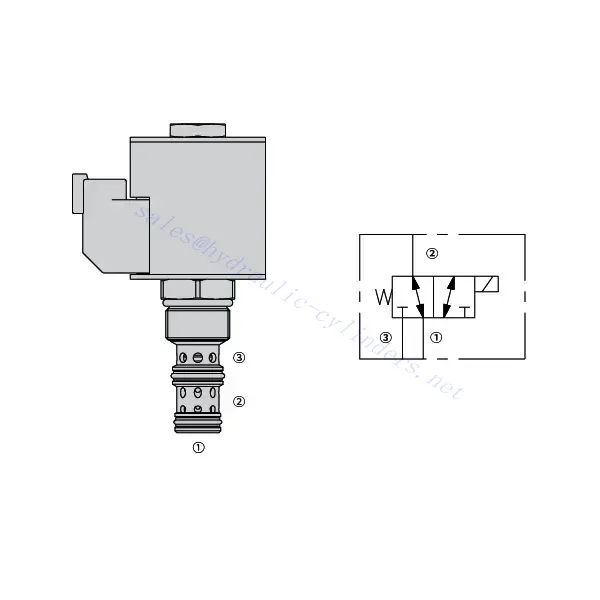
30SD10-34 Solenoid Directional Valve

The 30SD10-34 solenoid directional valve is a cutting-edge industrial component designed to provide precise and reliable fluid control in a wide range of applications. With its advanced features, durable construction, and user-friendly design, this solenoid directional valve offers enhanced performance and efficiency.
The 30SD10-34 solenoid directional valve is a reliable and versatile component that offers precise fluid control in industrial applications. Its robust construction, precision control, and reliable performance make it an ideal choice for enhancing the efficiency and productivity of your fluid control systems. By following the recommended usage methods and maintenance guidelines, you can ensure optimal performance and longevity of the 30SD10-34 solenoid directional valve in your industrial operations.
30SD10-34 Solenoid Directional Valve Characteristics:
- Robust Construction: The 30SD10-34 solenoid directional valve is built with high-quality materials and meticulous craftsmanship, ensuring durability and longevity. Its robust construction allows it to withstand demanding industrial environments, providing reliable performance even under harsh conditions.
- Versatile Functionality: This solenoid directional valve offers versatile functionality, making it suitable for various applications. It effectively controls the direction of fluid flow, allowing precise and efficient operation in different industrial systems.
- Precision Control: With exceptional precision, the 30SD10-34 solenoid directional valve enables accurate control over fluid flow. It allows for precise regulation and adjustment of fluid direction and pressure, ensuring optimal performance and efficiency in industrial processes.
- Reliable Performance: This solenoid directional valve delivers reliable performance, minimizing the risk of system failures or interruptions. It operates dependably, contributing to increased productivity and reduced downtime in industrial operations.
30SD10-34 Solenoid Directional Valve Parameter:
| Pression nominale | 207 bars (3000 psi) | |
| Proof pressure | 350 bar (5075 psi) | |
| Débit de pointe | 22.7 L/min (6 gpm) | |
| Fluide | À base minérale ou synthétique avec propriétés lubrifiantes | |
| Temperature range ℃ | -54 à 107 ℃ (Joints en polyuréthane) | |
| -40 à 100 ℃ (joints Buna N) | ||
| -26 à 204 ℃ (Joints en fluorocarbone) | ||
| Plage de viscosité | 7,4 à 420 mm2/s | |
| Degré de contamination | Le niveau de pollution minimum est ISO4406 niveau 20/18/14, et le niveau 17/15/13 est recommandé pour prolonger la durée de vie | |
| fuite interne | ≤ 115 mL/min@207bar | |
| Cavité | VC10-3 | |
| Capacité nominale de la bobine | Continu de 85% à 115% de tension nominale | |
| Response time | First indication of change of state with 100% voltage supplied at80% of nominal flow rating:Energized: 60 msec. ; De-energized: 10 msec. | |
| Consommation initiale de courant de la bobine à 20 ℃ | Bobine électronique | 1,7 A à 12 V CC ; 0,85 A à 24 V CC |
| Bobine D | 1,67 A à 12 V CC ; 0,83 A à 24 V CC | |
| Tension d'appel minimale | 85% de pression nominale à 207 bar | |
30SD10-34 Solenoid Directional Valve Advantages:
• Bobine nominale à service continu
• Construction efficace à armature humide
• Les cartouches sont interchangeables en termes de tension
• Bobines électroniques étanches en option classées IP69K
• All ports may be fully pressurized
• Cavité commune industrielle
• Pièces trempées pour une longue durée de vie et une faible fuite
Usage Method Of 30SD10-34 Solenoid Directional Valve:
- Integration into System: Integrate the 30SD10-34 solenoid directional valve into the fluid control system following the manufacturer’s guidelines and specifications. Ensure proper alignment and connection between the valve and other system components to achieve optimal performance.
- Electrical Connection: Establish a secure electrical connection for the solenoid directional valve. Refer to the provided wiring diagram and ensure correct polarity to prevent any electrical malfunctions. Follow safety guidelines when working with electrical connections.
- Fluid Flow Direction Control: Utilize the solenoid directional valve to control the direction of fluid flow. The valve is typically equipped with a lever or actuator for manual adjustment. Alternatively, it can be integrated into an automated control system for remote operation.
- Pressure Adjustment: Employ the solenoid directional valve to regulate fluid pressure within the system. By adjusting the valve’s settings, you can achieve the desired pressure levels for optimal performance and efficiency.
How To Plumb Auto Cycle Hydraulic Valve?
Plumbing an auto-cycle hydraulic valve requires careful attention to ensure proper installation and functionality. Follow these steps to plumb an auto-cycle hydraulic valve effectively:
- Rassemblez les outils et matériaux nécessaires : Before you begin, make sure you have all the required tools and materials, including hydraulic hoses, fittings, adapters, Teflon tape, wrenches, and a hydraulic fluid reservoir.
- Identify The Valve Ports: Examine the auto-cycle hydraulic valve to identify the different ports. Typically, there will be inlet ports, outlet ports, and possibly additional ports for pressure relief or auxiliary functions.
- Determine The Hydraulic Fluid Flow Direction: Determine the desired flow direction of the hydraulic fluid through the valve. This information is crucial for correctly connecting the inlet and outlet ports.
- Install Fittings And Adapters: Install the appropriate fittings and adapters onto the valve ports. Ensure they are tightened securely, but be careful not to overtighten and damage the threads.
- Apply Teflon Tape: Wrap Teflon tape around the threads of the fittings and adapters. This helps create a tight seal and prevents leaks.
- Connect Hydraulic Hoses: Attach hydraulic hoses to the fittings and adapters on the valve ports. Ensure the hoses are suitable for the hydraulic system’s pressure rating and are of the correct length.
- Secure Hose Connections: Use hose clamps or other suitable methods to secure the hydraulic hoses to the fittings. This prevents the hoses from coming loose during operation.
- Route The Hydraulic hoses: Carefully route the hydraulic hoses to connect the auto-cycle hydraulic valve to the hydraulic fluid reservoir and other hydraulic components, such as cylinders or motors. Avoid sharp bends or kinks in the hoses that could restrict fluid flow.
- Check For Leaks: Once all connections are made, check for leaks. Start by slowly pressurizing the system and inspecting each connection point. If you notice any leaks, tighten the fittings or replace faulty components as necessary.
- Fill The Hydraulic Fluid Reservoir: Fill the hydraulic fluid reservoir with the recommended type and quantity of hydraulic fluid. Refer to the manufacturer’s guidelines for the appropriate fluid specifications.
- Bleed Air From The System: B bleed any air trapped in the hydraulic system to ensure proper operation. Follow the manufacturer’s instructions for bleeding procedures, which typically involve cycling the design and opening bleed valves.
- Test The System: With the plumbing complete, test the auto-cycle hydraulic valve and the overall system’s performance. Verify that the valve functions as intended and that fluid flow is smooth and consistent.
Capacité de l'usine :
(1) Assemblage
Nous disposons d'une plateforme d'assemblage indépendante de recherche et développement de premier ordre. Notre atelier de production de vérins hydrauliques dispose de quatre lignes d'assemblage semi-automatiques de vérins de levage et d'une ligne d'assemblage automatique de vérins d'inclinaison, pour une capacité de production annuelle prévue d'un million de pièces. L'atelier de vérins spéciaux est équipé d'un système d'assemblage de nettoyage semi-automatique de diverses spécifications, d'une capacité de production annuelle prévue de 200 000 pièces et dispose d'équipements d'usinage CNC de pointe, d'un centre d'usinage, d'équipements spéciaux d'usinage de haute précision, d'une machine de soudage robotisée, d'une machine de nettoyage automatique, d'une machine d'assemblage automatique de vérins et d'une ligne de peinture automatique. Nous disposons de plus de 300 équipements critiques. L'allocation optimale et l'utilisation efficace des ressources garantissent la précision et la qualité des produits.


(2) Usinage
L'atelier d'usinage est équipé d'un centre de tournage sur rail incliné personnalisé, d'un centre d'usinage, d'une machine à honer à grande vitesse, d'un robot de soudage et d'autres équipements connexes, qui peuvent traiter des tubes cylindriques d'un diamètre intérieur maximal de 400 mm et d'une longueur maximale de 6 mètres.


(3) Soudage


(4) Peinture et revêtement
Avec des lignes de revêtement de peinture à base d'eau automatiques à cylindre de petite et moyenne taille, pour réaliser le chargement et le déchargement automatiques par robot et la pulvérisation automatique, la capacité de conception est de 4 000 pièces par équipe ;
Nous disposons également d'une ligne de production de peinture semi-automatique pour gros cylindres, alimentée par une chaîne de traction, d'une capacité de conception de 60 caisses par équipe.


(5) Essais
Nous disposons d'installations d'inspection et de bancs d'essai de premier ordre pour garantir que les performances de la bouteille sont conformes aux exigences.


Nous sommes l'un des meilleurs fabricants de vérins hydrauliques. Nous proposons une gamme complète de vérins hydrauliques. Nous fournissons également les vérins correspondants. boîtes de vitesses agricolesNous exportons nos produits dans le monde entier et nous avons acquis une excellente réputation grâce à la qualité supérieure de nos produits et à notre service après-vente. Nous invitons nos clients, nationaux et internationaux, à nous contacter pour négocier, échanger des informations et… coopérer avec nous!