
4WRKE Series Pilot Operated Proportional Directional Hydraulic Valve
En tant que fabricant, fournisseur et exportateur de produits mécaniques, nous proposons des vérins hydrauliques et de nombreux autres produits.
N'hésitez pas à nous contacter pour plus de détails.
Courrier :sales@hydraulic-cylinders.net
Fabricant fournisseur exportateur de vérins hydrauliques.
4WRKE Series Pilot Operated Proportional Directional Hydraulic Valve
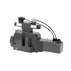
The 4WRKE series pilot-operated proportional directional hydraulic valve is a cutting-edge hydraulic component designed to provide superior precision, control, and efficiency in hydraulic systems. With its advanced pilot-operated proportional control technology, this valve enables accurate flow regulation and seamless directional changes.
The 4WRKE series pilot-operated proportional directional hydraulic valve empowers hydraulic systems with precise flow control, versatile directional changes, and energy efficiency. Its pilot-operated proportional control technology ensures accurate and responsive flow adjustment, while the high flow capacity guarantees reliable performance even in demanding applications. By following the recommended usage methods and maintenance guidelines, you can maximize the benefits and longevity of the 4WRKE series valve, elevating your hydraulic system to new levels of precision and control. Upgrade your hydraulic setup today and experience the power of the 4wrke series pilot-operated proportional directional hydraulic valve.
4WRKE Series Pilot Operated Proportional Directional Hydraulic Valve Key Characteristics:
- Commande proportionnelle pilotée
- The 4WRKE series valve utilizes pilot-operated proportional control technology, allowing precise and proportional flow adjustment based on control signals.
- Cette fonctionnalité garantit un contrôle précis et réactif, ce qui améliore les performances du système, réduit la consommation d'énergie et accroît la productivité.
- Commande directionnelle polyvalente
- Cette vanne offre un contrôle polyvalent de la direction du fluide hydraulique, ce qui la rend adaptée à une large gamme d'applications.
- Il permet l'activation et la désactivation en douceur des composants hydrauliques tels que les cylindres, les moteurs et les actionneurs dans différentes directions, améliorant ainsi la flexibilité et l'adaptabilité du système.
- Capacité de débit élevée
- The 4WRKE series valve is engineered to handle high flow rates, making it ideal for applications that require substantial hydraulic power.
- Sa construction robuste garantit des performances fiables même dans des conditions exigeantes, assurant un contrôle de débit constant et efficace.
- Efficacité énergétique
- Grâce à l'intégration d'une commande proportionnelle pilotée, cette vanne minimise les pertes de charge et optimise la consommation d'énergie.
- Cela contribue à réduire la consommation d'énergie, ce qui engendre des économies et des avantages environnementaux.
4WRKE Series Pilot Operated Proportional Directional Hydraulic Valve Parameter:
| Général | |||||||||
| Taille | 10 | 16 | 25 | 27 | 32 | 35 | |||
| Installation and commissioning guidelines | facultatif, de préférence horizontal | ||||||||
| Plage de température de stockage | °C | – 20 to + 80 | |||||||
| Plage de température ambiante | °C | -20 to + 50 | |||||||
| Poids | kg | 8.7 | 11.2 | 16.8 | 20 | 37.2 | 72 | ||
| Hydraulique ( measured at p=100bar,with HLP46 at ϑoil =40℃ ±5℃) | |||||||||
| Pression de service | -Pilot control valve | Pilot oil supply | bar | 25 to 315 | |||||
| -Main valve | Port P A B | bar | Up to 315 | Up to 350 | Up to 350 | Up to 210 | Up to 350 | Up to 350 | |
| Pression de retour | Port T
(Pilot oil drain) |
Internal | bar | Static < 10 | |||||
| External | bar | Up to 315 | Up to 250 | Up to 250 | Up to 210 | Up to 250 | Up to 250 | ||
| Port Y | bar | Static < 10 | |||||||
| Nominal flow qVnom ±10% at Δp=10bar (Δp = valve pressure differential) |
L/min | 25 50 | – 125 | – 220 | – – | – 440 | – | ||
| 100 | 180 | 350 | 500 | 600 | 1000 | ||||
| Flow of main valve (max. permissible) | L/min | 170 | 460 | 870 | 1000 | 1600 | 3000 | ||
| Pilot oil flow at port X or Y with a step form of input signal from 0 to 100 % (315 bar) | L/min | 4.1 | 8.5 | 11.7 | 11.7 | 13 | 13 | ||
| Fluide sous pression | Mineral oil(HL,HLP)to DIN 51 524 Phosphate ester (HFD-R) | ||||||||
| Plage de température du fluide | °C | 10 to 80, preferably 40 to 50 | |||||||
| Plage de viscosité | mm2/s | 20 to 380, preferably 30 to 45 | |||||||
| Degré de contamination | Maximum permissible degree of contamination: NAS 1638. | A filter with a minimum retention rate of βx = 75 is recommended | |||||||
| Pilot control valve | Class 7 | x = 5 | |||||||
| Vanne principale | Class 9 | x = 7 | |||||||
| Hystérèse | % | ≤1 | |||||||
| Sensibilité de la réponse | % | ≤0,5 | |||||||
| Électrique | |||||||||
| Type de tension | DC | ||||||||
| raccordement électrique | Plug-in connector to DIN EN175 201-804 | ||||||||
| Power, max. | W | 72 (average = 24W) | |||||||
| électronique de contrôle | Integrated into the valve | ||||||||
4WRKE Series Pilot Operated Proportional Directional Hydraulic Valve Advantages:
• Pilot-operated two-stage proportional directional valve with electrical position feedback of the main spool, used to control the size and direction of the liquid flow
• Sub-plate mounting type connection structure, connection size conforms to ISO 4401 standard
• Spring centred main spool
• With integrated proportional amplifier
• The pilot control is a single-stage proportional directional valve
• The pilot valve is a threaded proportional solenoid, and the coil can be disassembled separately
Usage Method Of 4WRKE Series Pilot Operated Proportional Directional Hydraulic Valve:
- Évaluation du système
- Évaluez votre système hydraulique et identifiez les exigences spécifiques en matière de débit et de contrôle directionnel.
- Determine if the 4WRKE Series Valve is suitable based on its flow capacity, pressure rating, and compatibility with your system.
- Sélection de vannes
- Select the appropriate variant of the 4WRKE Series Valve based on your system parameters, flow requirements, and directional control needs.
- Tenez compte de facteurs tels que le débit maximal, la pression nominale, le temps de réponse et les conditions de fonctionnement.
- Installation
- Suivez attentivement les instructions d'installation du fabricant, en veillant à un alignement correct et à une fixation sécurisée de la vanne.
- Réalisez des raccords étanches et assurez-vous du bon alignement du sens d'écoulement pour garantir des performances optimales.
- Connexion du signal de commande
- Raccordez les fils de signal de commande de la vanne à un dispositif de commande approprié, tel qu'un amplificateur proportionnel ou une unité de commande électronique.
- Assurez-vous d'un câblage correct et d'une compatibilité entre la vanne et le dispositif de commande pour une régulation précise et réactive.
How To Clean Hydraulic Valve Lifters?
Cleaning hydraulic valve lifters is an important maintenance task that helps ensure proper engine performance and reduce noise caused by dirt or debris buildup. Here’s a step-by-step guide on how to clean hydraulic valve lifters:
- Rassemblez les outils et matériaux nécessaires :
- New engine oil
- Chiffons ou serviettes propres
- Engine degreaser or parts cleaner
- Small brush or toothbrush
- Plastic container or tray
- Préparation:
- Allow the engine to cool down completely before starting the cleaning process.
- Remove the valve cover or covers to access the hydraulic valve lifters. Refer to the manufacturer’s instructions or a repair manual for your specific engine to locate and remove the valve cover(s) properly.
- Removal of Hydraulic Valve Lifters:
- Identify the hydraulic valve lifters in the engine.
- One at a time, carefully remove the hydraulic valve lifters from their respective locations. Depending on your engine, you may need to remove other components or parts to access the lifters.
- Place each lifter in a plastic container or tray in the order they were removed. This will help ensure they are reinstalled correctly later.
- Cleaning the Lifters:
- Pour a small amount of engine degreaser or parts cleaner into a container.
- Place one hydraulic valve lifter into the container, ensuring it is fully submerged in the cleaner.
- Allow the lifter to soak for the recommended duration specified by the cleaner manufacturer. This usually ranges from 15 minutes to an hour.
- Use a small brush or toothbrush to gently scrub the lifter’s exterior surfaces, removing any deposits or dirt.
- Rinse the lifter thoroughly with clean water to remove any remaining cleaner or debris.
- Dry the lifter using a clean rag or towel. Ensure there are no traces of moisture before reinstallation.
- Reinstallation:
- Apply a small amount of fresh engine oil to the cleaned lifter’s exterior surface.
- Carefully place the lifter back into its original position in the engine, ensuring it is properly aligned and seated.
- Repeat the cleaning process for each hydraulic valve lifter, following the same steps.
- Once all the lifters are cleaned and reinstalled, make sure they are secured properly.
- Remontage:
- Reinstall the valve cover(s) according to the manufacturer’s instructions.
- Double-check that all components and parts are properly secured and tightened.
- Test and Inspection:
- Start the engine and let it run for a few minutes to ensure proper operation and to allow the lifters to refill with oil.
- Listen for any abnormal noises or ticking sounds that could indicate further issues.
- If noise or performance problems persist, it may be necessary to consult a professional mechanic for further diagnosis and repair.
Capacité de l'usine :
(1) Assemblage
Nous disposons d'une plateforme d'assemblage indépendante de recherche et développement de premier ordre. Notre atelier de production de vérins hydrauliques dispose de quatre lignes d'assemblage semi-automatiques de vérins de levage et d'une ligne d'assemblage automatique de vérins d'inclinaison, pour une capacité de production annuelle prévue d'un million de pièces. L'atelier de vérins spéciaux est équipé d'un système d'assemblage de nettoyage semi-automatique de diverses spécifications, d'une capacité de production annuelle prévue de 200 000 pièces et dispose d'équipements d'usinage CNC de pointe, d'un centre d'usinage, d'équipements spéciaux d'usinage de haute précision, d'une machine de soudage robotisée, d'une machine de nettoyage automatique, d'une machine d'assemblage automatique de vérins et d'une ligne de peinture automatique. Nous disposons de plus de 300 équipements critiques. L'allocation optimale et l'utilisation efficace des ressources garantissent la précision et la qualité des produits.


(2) Usinage
L'atelier d'usinage est équipé d'un centre de tournage sur rail incliné personnalisé, d'un centre d'usinage, d'une machine à honer à grande vitesse, d'un robot de soudage et d'autres équipements connexes, qui peuvent traiter des tubes cylindriques d'un diamètre intérieur maximal de 400 mm et d'une longueur maximale de 6 mètres.

(3) Soudage

(4) Peinture et revêtement
Avec des lignes de revêtement de peinture à base d'eau automatiques à cylindre de petite et moyenne taille, pour réaliser le chargement et le déchargement automatiques par robot et la pulvérisation automatique, la capacité de conception est de 4 000 pièces par équipe ;
Nous disposons également d'une ligne de production de peinture semi-automatique pour gros cylindres, alimentée par une chaîne de traction, d'une capacité de conception de 60 caisses par équipe.


(5) Essais
Nous disposons d'installations d'inspection et de bancs d'essai de premier ordre pour garantir que les performances de la bouteille sont conformes aux exigences.

Nous sommes l'un des meilleurs fabricants de vérins hydrauliques. Nous proposons une gamme complète de vérins hydrauliques. Nous fournissons également les vérins correspondants. boîtes de vitesses agricolesNous exportons nos produits dans le monde entier et nous avons acquis une excellente réputation grâce à la qualité supérieure de nos produits et à notre service après-vente. Nous invitons nos clients, nationaux et internationaux, à nous contacter pour négocier, échanger des informations et… coopérer avec nous!
Vérin hydraulique Application :
