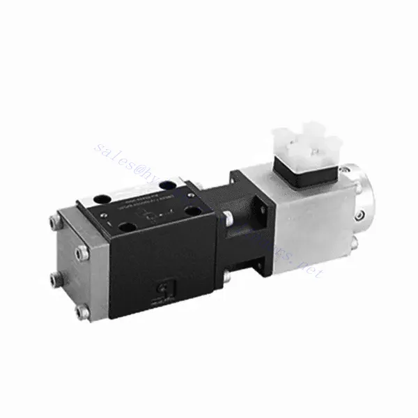
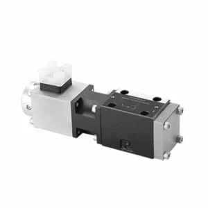
DBE6X(E) Series Proportional Pressure Relief Hydraulic Valve
En tant que fabricant, fournisseur et exportateur de produits mécaniques, nous proposons des vérins hydrauliques et de nombreux autres produits.
N'hésitez pas à nous contacter pour plus de détails.
Courrier :sales@hydraulic-cylinders.net
Fabricant fournisseur exportateur de vérins hydrauliques.
DBE6X(E) Series Proportional Pressure Relief Hydraulic Valve
The DBE6X(E) series proportional pressure relief hydraulic Valve is a cutting-edge component that provides accurate and dynamic pressure control in hydraulic systems. With its advanced proportional control technology, this valve ensures optimal performance, efficiency, and safety.
The DBETX series proportional pressure relief hydraulic valve empowers hydraulic systems with precise pressure control, enhanced efficiency, and equipment protection. With its commensurate pressure relief capabilities, this valve ensures optimal performance across various applications. By following the recommended usage methods and maintenance guidelines, you can maximize the benefits and reliability of the DBETX series valve, elevating the performance and control of your hydraulic system. Upgrade your hydraulic setup today and experience superior pressure regulation with the DBETX series proportional pressure relief hydraulic valve.
Caractéristiques principales de la soupape hydraulique de décharge de pression proportionnelle série DBE6X(E) :
- Soulagement proportionnel de la pression :
- The DBE6X(E) series valve offers precise and proportional pressure relief, allowing dynamic hydraulic pressure control.
- Il assure une régulation précise de la pression en réponse aux variations de charge, évitant ainsi la surcharge du système et protégeant les composants hydrauliques.
- Amélioration de l'efficacité du système :
- Cette vanne permet un contrôle précis de la pression hydraulique, ce qui améliore l'efficacité du système et réduit la consommation d'énergie.
- En maintenant les niveaux de pression souhaités, il minimise les fluctuations de pression, optimise les performances du système et réduit les coûts d'exploitation.
- Sécurité et protection des équipements :
- The DBE6X(E) Series Valve acts as a protective mechanism by limiting the pressure within the hydraulic system, safeguarding equipment and operators.
- Il empêche une accumulation excessive de pression, réduisant ainsi le risque d'endommagement des composants, de défaillances du système et d'accidents potentiels.
- Fonctionnalité de contrôle proportionnel :
- With its proportional control technology, the DBE6X(E) series valve offers smooth and precise pressure adjustment.
- Il permet un contrôle de la pression en temps réel, assurant une intégration transparente dans divers systèmes et applications hydrauliques.
DBE6X(E) Series Proportional Pressure Relief Hydraulic Valve Parameter:
| Général | ||||||
| Construction | Phase pilote | soupape à clapet | ||||
| Scène principale | vanne à tiroir | |||||
| Actionnement | Électrovanne proportionnelle sans commande de position, amplificateur externe | |||||
| Type de connexion | Sous-plaque, configuration des trous de montage NG6 (SIO 4401-03-02-094) | |||||
| Position d'installation | Facultatif | |||||
| Plage de température des circonstances | °C | -20 à +50 | ||||
| Poids | kg | 2.2 | ||||
| Résistance aux vibrations, condition de test | Max. 25 g, agité dans les 3 dimensions (24 h) | |||||
| Hydraulique (mesuré avec HLP 46, huile = 40℃ ±5℃) : | ||||||
| Fluide sous pression | Hydraulic oil to DIN 51524…535,other fluids after prior consultation | |||||
| Plage de viscosité | recommandé | mm²/s | 20…100 | |||
| max. autorisé | mm²/s | 10…800 | ||||
| Plage de température du fluide sous pression | °C | -20 à +80 | ||||
| Degré maximal de contamination autorisé du fluide sous pression Classe de pureté selon ISO 4406 (c) | Classe 18/16/13 | |||||
| Sens du courant | Voir le symbole | |||||
| Pression de réglage maximale (à Qmaxx = 1 L/min) | bar | 80 | 180 | 250 | 315 | |
| Min. pression réglable (et Qmin = 1 L/min) | bar | 7 | 8 | 9 | 10 | |
| Pression de service max. | bar | Port P : 315 | ||||
| Port T : 250 | ||||||
| Niveau de limitation de pression mécanique maximale, par exemple lorsque le courant du solénoïde I > Imax | bar | < 90 | < 190 | < 260 | < 235 | |
| Débit d'huile pilote | L/min | environ 0,6 | ||||
| Débit max. | L/min | 40 | ||||
| données électriques | ||||||
| Facteur de durée cyclique | % | 100 ED | ||||
| Degré de protection | Indice de protection IP 65 selon les normes DIN 40050 et IEC 14434/5 | |||||
| connexion du solénoïde | Connecteur enfichable conforme à la norme DIN 43650/ISO 4400, M16X1,5 (2P+PE) | |||||
| Vanne de type solénoïde | 0,8A | 2,5 A | ||||
| Courant maximal du solénoïde | Imax | 0,8A | 2,5 A | |||
| Résistance de la bobine R20 | Ω | 22 | 3 | |||
| Consommation électrique maximale à la charge et à la température de fonctionnement du 100% | Virginie | 25 | 30 | |||
| Statique/Dynamique | ||||||
| Hystérèse | % | ≤ 4 | ||||
| Amplitude d'inversion | % | ≤3 | ||||
| Tolérance de fabrication pour Pmax | % | ≤10 | ||||
| Changement de signal du temps de réponse 100% | MS | Marche 200 / Arrêt | ||||
DBE6X(E) Series Proportional Pressure Relief Hydraulic Valve Advantages:
• Soupape pilote pour limiter la pression du système (contrôle de l'huile interne uniquement)
• Réglable en contrôlant le courant de la bobine selon la courbe caractéristique et l'unité de commande électronique sélectionnée
• Type de solénoïde Imax = 0,8 A ou 2,5 A
• En cas de défaillance de l'unité de commande électronique, la protection contre les surcharges peut fonctionner au maximum (courant de la bobine > Imax).
• Utilisé pour le montage sur sous-plaque de vanne, le trou de montage est conforme à la norme ISO 441-03-02-0-94.
• Les prises de câble sont conformes à la norme DIN 43650-AM2
• Unité de commande électronique externe avec fonction de réglage de rampe et de vanne VT-SSPA1-508/525-L2X/V0/*
Usage Method Of DBE6X(E) Series Proportional Pressure Relief Hydraulic Valve:
- Évaluation du système :
- Évaluez votre système hydraulique et identifiez les exigences spécifiques en matière de contrôle de la pression.
- Determine if the DBE6X(E) series valve is compatible with your system based on its pressure range, flow capacity, and other specifications.
- Sélection de la vanne :
- Choose the appropriate DBE6X(E) series valve variant based on your system parameters, pressure range, and flow requirements.
- Tenir compte de la pression nominale maximale, du temps de réponse et des conditions de fonctionnement.
- Installation:
- Suivez attentivement les instructions d'installation du fabricant, en veillant à un alignement correct et à une fixation sécurisée de la vanne.
- Raccordez la vanne au système hydraulique en veillant à l'étanchéité des connexions et au bon alignement du sens d'écoulement.
- Réglage de la pression :
- Utilize the proportional control signal or adjustment mechanism provided with the DBE6X(E) series valve to set the desired pressure relief level.
- Réglez la vanne par paliers, en surveillant les indications du manomètre et la réponse du système pour obtenir un contrôle précis de la pression.
How To Adjust Hydraulic Flow Control Valve?
Adjusting a hydraulic pressure relief valve allows you to set the desired maximum pressure in a hydraulic system. This is important for maintaining system integrity and preventing damage to components. Here’s a step-by-step guide on how to adjust a hydraulic pressure relief valve:
- Identifier la soupape de décharge de pression :
- Locate the pressure relief valve in your hydraulic system. It is typically installed in the hydraulic line and often near the pump or control valve.
- Comprendre la conception de la vanne :
- Familiarisez-vous avec la conception spécifique de la soupape de décharge de pression que vous utilisez. Différentes soupapes peuvent avoir des mécanismes de réglage variés, tels qu'un bouton, une vis ou un contre-écrou.
- Determine the Desired Pressure:
- Assess the requirements of your hydraulic system and determine the desired maximum pressure. This will guide you in adjusting the pressure relief valve accurately.
- Préparer le système :
- Avant tout réglage, coupez le système hydraulique et relâchez la pression en déplaçant les leviers de commande d'avant en arrière ou en suivant la procédure recommandée par le fabricant.
- Localisez le mécanisme de réglage :
- Identifiez le mécanisme de réglage de la soupape de décharge de pression. Il peut s'agir d'un bouton, d'une vis ou d'un contre-écrou situé sur le corps de la soupape ou à proximité.
- Réglez la vanne :
- If the valve has a knob or handle, turn it clockwise to increase the pressure relief setting or counterclockwise to decrease it. If the valve has a screw, turn it clockwise to increase the pressure relief or counterclockwise to decrease it.
- Effectuez des ajustements progressifs :
- When adjusting the pressure relief valve, make small, incremental changes to avoid sudden or drastic variations in pressure. This allows you to fine-tune the maximum pressure and achieve the desired performance.
- Observez le système :
- With each adjustment, observe the hydraulic system and its components. Pay attention to the pressure gauge readings to see if they align with the desired maximum pressure.
- Tester et vérifier :
- Operate the hydraulic system and monitor the pressure to ensure that it remains within the desired range. Check for any pressure fluctuations or irregularities that may indicate the need for further adjustment.
- Verrouiller le réglage :
- Once you have achieved the desired pressure relief setting, secure the adjustment mechanism to prevent unintended changes. Some valves may have a locking nut or set screw that can be tightened to hold the adjustment in place.
- Monitor and Revisit:
- Regularly monitor the pressure relief valve and the hydraulic system. If there are changes in the system or if the desired maximum pressure needs to be adjusted, revisit the pressure relief valve and repeat the adjustment process as needed.
Capacité de l'usine :
(1) Assemblage
Nous disposons d'une plateforme d'assemblage indépendante de recherche et développement de premier ordre. Notre atelier de production de vérins hydrauliques dispose de quatre lignes d'assemblage semi-automatiques de vérins de levage et d'une ligne d'assemblage automatique de vérins d'inclinaison, pour une capacité de production annuelle prévue d'un million de pièces. L'atelier de vérins spéciaux est équipé d'un système d'assemblage de nettoyage semi-automatique de diverses spécifications, d'une capacité de production annuelle prévue de 200 000 pièces et dispose d'équipements d'usinage CNC de pointe, d'un centre d'usinage, d'équipements spéciaux d'usinage de haute précision, d'une machine de soudage robotisée, d'une machine de nettoyage automatique, d'une machine d'assemblage automatique de vérins et d'une ligne de peinture automatique. Nous disposons de plus de 300 équipements critiques. L'allocation optimale et l'utilisation efficace des ressources garantissent la précision et la qualité des produits.


(2) Usinage
L'atelier d'usinage est équipé d'un centre de tournage sur rail incliné personnalisé, d'un centre d'usinage, d'une machine à honer à grande vitesse, d'un robot de soudage et d'autres équipements connexes, qui peuvent traiter des tubes cylindriques d'un diamètre intérieur maximal de 400 mm et d'une longueur maximale de 6 mètres.

(3) Soudage

(4) Peinture et revêtement
Avec des lignes de revêtement de peinture à base d'eau automatiques à cylindre de petite et moyenne taille, pour réaliser le chargement et le déchargement automatiques par robot et la pulvérisation automatique, la capacité de conception est de 4 000 pièces par équipe ;
Nous disposons également d'une ligne de production de peinture semi-automatique pour gros cylindres, alimentée par une chaîne de traction, d'une capacité de conception de 60 caisses par équipe.


(5) Essais
Nous disposons d'installations d'inspection et de bancs d'essai de premier ordre pour garantir que les performances de la bouteille sont conformes aux exigences.

Nous sommes l'un des meilleurs fabricants de vérins hydrauliques. Nous proposons une gamme complète de vérins hydrauliques. Nous fournissons également les vérins correspondants. boîtes de vitesses agricolesNous exportons nos produits dans le monde entier et nous avons acquis une excellente réputation grâce à la qualité supérieure de nos produits et à notre service après-vente. Nous invitons nos clients, nationaux et internationaux, à nous contacter pour négocier, échanger des informations et… coopérer avec nous!
Vérin hydraulique Application :
