

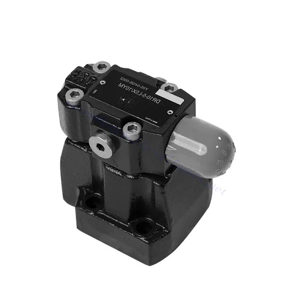
Réducteur de pression hydraulique piloté série DR
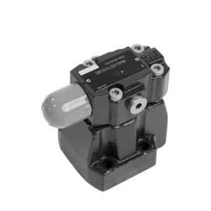

La vanne hydraulique de réduction de pression pilotée de la série DR est un composant fiable et de haute qualité conçu pour assurer un contrôle précis de la pression dans les systèmes hydrauliques. Grâce à son mécanisme piloté innovant et à ses performances exceptionnelles, cette vanne réduit la pression hydraulique avec précision pour répondre aux exigences spécifiques du système.
La vanne hydraulique de réduction de pression pilotée série DR est une solution haute performance pour un contrôle précis de la pression dans les systèmes hydrauliques. Grâce à sa conception pilotée, à sa régulation précise de la pression, à sa large plage de pression et à son débit élevé, cette vanne assure une réduction de pression efficace et précise tout en préservant les composants du système. En suivant les recommandations d'utilisation et de maintenance, la vanne série DR offre des performances fiables, prolongeant ainsi la durée de vie des systèmes hydrauliques. Améliorez votre système hydraulique avec la vanne hydraulique de réduction de pression pilotée série DR et bénéficiez d'un contrôle optimal de la pression pour une efficacité et une productivité accrues.
Principales caractéristiques de la vanne hydraulique de réduction de pression pilotée série DR :
- Conception pilotée :
- La vanne de la série DR est dotée d'une conception pilotée, offrant une réduction de pression précise, fiable et stable dans les systèmes hydrauliques.
- It utilizes a separate control circuit, the pilot circuit, to regulate the main valve’s opening and control the pressure.
- Contrôle précis de la pression :
- Cette vanne offre une précision exceptionnelle dans le contrôle de la pression, permettant aux systèmes hydrauliques de fonctionner dans les limites de pression souhaitées.
- Il maintient des niveaux de pression constants, évitant ainsi la surpression et protégeant les composants sensibles du système.
- Large plage de pression :
- La vanne de la série DR est disponible dans différentes plages de pression, ce qui la rend adaptée à diverses applications hydrauliques.
- Il permet une personnalisation pour répondre aux exigences spécifiques du système et optimiser les performances.
- Capacité de débit élevée :
- Cette vanne présente une excellente capacité de débit, lui permettant de gérer des débits élevés sans compromettre la précision du contrôle de la pression.
- Il assure une régulation efficace des fluides et un fonctionnement ininterrompu du système.
Paramètre de la vanne hydraulique de réduction de pression pilotée série DR :
| Fluide | Huile minérale adaptée aux joints NBR et FKM | |||||||
| Ester phosphate pour joint FKM | ||||||||
| Plage de température du fluide | °C | -30 à +80 (joints NBR) | ||||||
| -20 à +80 (joints FKM) | ||||||||
| Plage de viscosité | mm2/s | 10 à 800 | ||||||
| Degré de contamination | Degré maximal admissible de contamination des fluides : Classe 9. NAS 1638 ou 20/18/15, ISO4406 | |||||||
| Pression de service max. | Port B | bar | 350 | |||||
| Plage de pression de fonctionnement | Port A | bar | 10 à 350 | |||||
| Pression de support maximale | Port Y | bar | 350 (uniquement pour sans clapet anti-retour) ; 315 (avec clapet anti-retour) | |||||
| Réglage de la pression | Max. | bar | 50;100;200;315;350 | |||||
| Min. | bar | En rapport avec le débit (se référer à la courbe caractéristique) | ||||||
| Taille | DR10 | DR15 | DR20 | DR25 | DR30 | |||
| Débit max. | Montage de la sous-plaque de base | L/min | 150 | – | 300 | – | 400 | |
| connexion filetée | L/min | 150 | 300 | 300 | 400 | 400 | ||
| Position d'installation | Position d'installation | |||||||
| Taille | DR10 | DR15 | DR20 | DR25 | DR30 | |||
| Poids | Montage sur plaque de base | DR | kg | environ 3,6 | – | environ 5,3 | – | environ 8,2 |
| connexion filetée | DR…G | kg | environ 5,3 | environ 5,5 | environ 5,1 | environ 5,0 | environ 5,0 | |
| RDC | kg | environ 1,2 | ||||||
| DRC30 | kg | environ 1,5 | ||||||
Avantages de la vanne hydraulique de réduction de pression pilotée série DR :
• Utilisé pour le montage de la sous-plaque inférieure
• La face d'installation est conforme aux normes DIN24340 D et ISO5781
• Utilisé dans l'installation du bloc de passage d'huile
• Utilisé dans les connexions à vis
• Cinq plages de pression
• Deux types de réglage : bouton, vis de réglage avec capuchon de protection
• Valve unidirectionnelle en option (utilisée uniquement pour le montage de la sous-plaque inférieure)
Méthode d'utilisation de la vanne hydraulique de réduction de pression pilotée série DR :
- Analyse du système :
- Effectuer une analyse complète du système hydraulique pour déterminer les exigences spécifiques de contrôle de pression.
- Tenez compte de la pression de fonctionnement maximale, de la plage de pression souhaitée et des débits.
- Sélection de la vanne :
- Select the appropriate DR series valve variant based on the system’s pressure control specifications.
- Tenez compte de la pression nominale, de la capacité de débit et de la compatibilité avec les autres composants du système.
- Installation:
- Follow the manufacturer’s instructions to correctly install the hydraulic system’s DR series pilot-operated pressure-reducing valve.
- Assurez un alignement correct et des connexions sécurisées pour éviter les fuites et optimiser les performances.
- Étalonnage:
- Calibrez la vanne pour régler la pression en aval souhaitée.
- Utilize pressure gauges or other measurement devices to adjust the valve’s pilot circuit accurately.
Comment fonctionne une soupape de décharge hydraulique ?
A hydraulic relief valve is a crucial component in hydraulic systems that protects the system from excessive pressure by diverting excess fluid flow back to the reservoir. It operates based on the principle of utilizing a spring-loaded mechanism to control the pressure level within the system. Let’s explore how a hydraulic relief valve works:
- Construction de la vanne :
- Une soupape de décharge hydraulique se compose d'un corps de soupape, d'un clapet ou d'une bobine à ressort et d'un ressort réglable.
- Le corps de la vanne contient des orifices de fluide pour l'entrée, la sortie et une conduite de vidange ou de retour vers le réservoir.
- Réglage de la pression :
- La soupape de décharge est dotée d'un ressort réglable qui détermine la pression à laquelle la soupape s'ouvre.
- Le réglage de la tension du ressort peut définir la pression nécessaire pour ouvrir la vanne et soulager l'excès de contrainte.
- Surveillance de la pression du système :
- Lorsque le système hydraulique fonctionne, la pression augmente en raison de facteurs tels que le débit de la pompe, la résistance de charge ou les changements de température.
- La soupape de décharge surveille en permanence la pression du système via son orifice d'admission.
- Seuil de pression :
- Lorsque la pression du système atteint ou dépasse le seuil de pression défini, une force est exercée sur le clapet ou la bobine contre la tension du ressort.
- Ouverture de la vanne :
- Une fois que la force exercée par la pression du système dépasse la tension du ressort, la soupape de décharge s'ouvre.
- This creates a path for excess fluid to flow from the system’s high-pressure side to the low-pressure side or directly back to the reservoir.
- Égalisation de la pression :
- La soupape de décharge détourne l'excès de débit de fluide, permettant ainsi à la pression dans le système de s'égaliser et empêchant la surpression.
- Cela protège les composants du système contre les dommages potentiels et garantit un fonctionnement sûr.
- Fermeture de la vanne :
- Once the pressure drops below the set threshold, the spring’s tension overcomes the force exerted by the system pressure.
- La soupape de décharge se ferme, bloquant le trajet d'écoulement du fluide et rétablissant le débit normal du fluide hydraulique à travers le système.
- Surveillance continue :
- La soupape de décharge surveille en permanence la pression du système, s'ouvrant et se fermant si nécessaire pour maintenir la pression dans la plage souhaitée.
- Cette réponse dynamique garantit que le système fonctionne en toute sécurité et évite les pics ou fluctuations de pression.
Capacité de l'usine :
(1) Assemblage
Nous disposons d'une plateforme d'assemblage indépendante de recherche et développement de premier ordre. Notre atelier de production de vérins hydrauliques dispose de quatre lignes d'assemblage semi-automatiques de vérins de levage et d'une ligne d'assemblage automatique de vérins d'inclinaison, pour une capacité de production annuelle prévue d'un million de pièces. L'atelier de vérins spéciaux est équipé d'un système d'assemblage de nettoyage semi-automatique de diverses spécifications, d'une capacité de production annuelle prévue de 200 000 pièces et dispose d'équipements d'usinage CNC de pointe, d'un centre d'usinage, d'équipements spéciaux d'usinage de haute précision, d'une machine de soudage robotisée, d'une machine de nettoyage automatique, d'une machine d'assemblage automatique de vérins et d'une ligne de peinture automatique. Nous disposons de plus de 300 équipements critiques. L'allocation optimale et l'utilisation efficace des ressources garantissent la précision et la qualité des produits.


(2) Usinage
L'atelier d'usinage est équipé d'un centre de tournage sur rail incliné personnalisé, d'un centre d'usinage, d'une machine à honer à grande vitesse, d'un robot de soudage et d'autres équipements connexes, qui peuvent traiter des tubes cylindriques d'un diamètre intérieur maximal de 400 mm et d'une longueur maximale de 6 mètres.


(3) Soudage


(4) Peinture et revêtement
Avec des lignes de revêtement de peinture à base d'eau automatiques à cylindre de petite et moyenne taille, pour réaliser le chargement et le déchargement automatiques par robot et la pulvérisation automatique, la capacité de conception est de 4 000 pièces par équipe ;
Nous disposons également d'une ligne de production de peinture semi-automatique pour gros cylindres, alimentée par une chaîne de traction, d'une capacité de conception de 60 caisses par équipe.


(5) Essais
Nous disposons d'installations d'inspection et de bancs d'essai de premier ordre pour garantir que les performances de la bouteille sont conformes aux exigences.


Nous sommes l'un des meilleurs fabricants de vérins hydrauliques. Nous proposons une gamme complète de vérins hydrauliques. Nous fournissons également les vérins correspondants. boîtes de vitesses agricolesNous exportons nos produits dans le monde entier et nous avons acquis une excellente réputation grâce à la qualité supérieure de nos produits et à notre service après-vente. Nous invitons nos clients, nationaux et internationaux, à nous contacter pour négocier, échanger des informations et… coopérer avec nous!