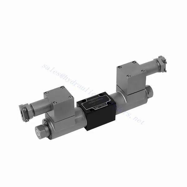
GWE Series Explosion-proof Solenoid Directional Hydraulic Valve
En tant que fabricant, fournisseur et exportateur de produits mécaniques, nous proposons des vérins hydrauliques et de nombreux autres produits.
N'hésitez pas à nous contacter pour plus de détails.
Courrier :sales@hydraulic-cylinders.net
Fabricant fournisseur exportateur de vérins hydrauliques.
GWE Series Explosion-proof Solenoid Directional Hydraulic Valve
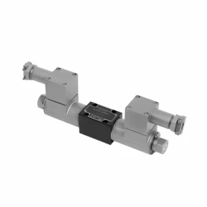
The GWE series explosion-proof solenoid directional hydraulic valve is a cutting-edge product designed to ensure safety and efficiency in hydraulic systems operating in hazardous environments. With its explosion-proof capabilities and reliable performance, this valve offers precise control, enhanced safety features, and optimal fluid flow management.
The GWE series explosion-proof solenoid directional hydraulic valve is a remarkable solution for achieving safety and efficiency in hydraulic systems operating in hazardous environments. With its explosion-proof design, solenoid technology, directional control capabilities, and versatility, this valve provides reliable performance and precise fluid flow management. By following the recommended usage methods and adhering to regular maintenance practices, the GWE series valve ensures safe and efficient operation in explosive atmospheres. Upgrade your hydraulic system with the GWE series explosion-proof solenoid directional hydraulic valve and experience the benefits of enhanced safety and optimized fluid flow control.
GWE Series Explosion-proof Solenoid Directional Hydraulic Valve Key Characteristics:
- Conception antidéflagrante :
- The GWE series hydraulic valve is precisely engineered to operate safely in explosive atmospheres, such as those containing flammable gases or dust.
- It complies with stringent safety standards and certifications, ensuring reliable performance and preventing potential ignition sources.
- Solenoid Technology:
- This hydraulic valve utilizes solenoid technology for precise control of fluid flow.
- The electromagnetic coil generates a magnetic field that actuates the valve, enabling quick response times and accurate positioning.
- Contrôle directionnel :
- The GWE series valve provides efficient directional control of hydraulic fluid flow, allowing for the activation and deactivation of specific hydraulic actuators.
- It ensures smooth and reliable operation of various hydraulic functions, such as cylinder extension and retraction or motor direction changes.
- Versatility and Compatibility:
- This hydraulic valve is highly versatile and compatible with various systems and applications.
- It can be integrated into industrial machinery, mobile equipment, and automation systems operating in hazardous environments.
GWE Series Explosion-proof Solenoid Directional Hydraulic Valve Parameter:
| Caractéristiques | NG6 | NG10 | ||
| Position d'installation | Facultatif | Facultatif | ||
| Température ambiante | °C | -30 to +50(NBR seal) | ||
| -20 to +50(FKM seal) | ||||
| Poids | électrovanne simple | kg | 2.6 | 5.9 |
| Électrovanne double | kg | 4.3 | 8.9 | |
| Pression de service maximale | Port P, A, B | bar | 350 | 315 |
| Port T | bar | 210 | ||
| When the working pressure exceeds the allowable pressure, the valves with symbols a and B must use T as the oil release port. | ||||
| Débit max. | L/min | 80 | 120 | |
| Type V | mm2 | / | 11(A/B → T);10.3(P → A/B) | |
| Flowarea (switching neutral position ) | Type Q | mm2 | pour le symbole Q 6% de section nominale | 2,5(A/B → T) |
| Type W | mm2 | pour le symbole W 3% de section nominale | 5.5(A/B → T) | |
| Fluide | Huile minérale adaptée aux joints NBR et FKM | |||
| Ester phosphate pour joint FKM | ||||
| Plage de température du fluide | °C | -30 à +80 (joint NBR) | ||
| -20 à +80 (sceau FKM) | ||||
| Plage de viscosité | mm2/s | 2,8 à 500 | ||
| Degré de contamination | Degré maximal admissible de contamination des fluides : Classe 9. NAS 1638 ou 20/18/15, ISO4406 | |||
GWE Series Explosion-proof Solenoid Directional Hydraulic Valve Advantages:
NG6
• Direct explosion proof solenoid slide valve as standard type
• La face de montage est conforme aux normes DIN 24340 A, ISO 4401 et CETOP-RP 121H.
• Wet DC explosion proof solenoid
• Explosion proof solenoid can rotate 90°
• Remplacer la bobine sans vidanger l'huile
NG10
• Explosion proof solenoid slide valve as standard typen
• La face de montage est conforme aux normes DIN 24340 A, ISO 4401 et CETOP-RP 121H.
• Wet DC explosion proof solenoid
• Explosion proof solenoid can rotate 90°
• Remplacer la bobine sans vidanger l'huile
Usage Method Of GWE Series Explosion-proof Solenoid Directional Hydraulic Valve:
- Hazardous Area Assessment:
- Conduct a thorough assessment of the hazardous area to identify the specific explosion-proof requirements and classification.
- Determine the appropriate safety measures and precautions needed to comply with the regulations.
- Sélection de la vanne :
- Select the GWE Series Valve with the appropriate specifications, considering pressure ratings, flow capacity, and voltage requirements.
- Ensure compatibility with the hydraulic system and the specific hazardous environment.
- Installation:
- Follow the manufacturer’s instructions for properly installing the GWE series valve in the hydraulic system.
- Ensure secure mounting and proper electrical connections, adhering to the recommended torque values and wiring guidelines.
- Control and Activation:
- Utilize the recommended control method, such as electrical signals or remote activation, to operate the GWE Series Valve.
- Connect the valve to a suitable power source and control system, following the provided wiring diagrams.
How Does A Hydraulic Check Valve Work?
A hydraulic check valve, also known as a one-way or non-return valve, is a crucial component in hydraulic systems that allows fluid flow in only one direction while preventing backflow. It ensures the proper operation and safety of hydraulic systems by preventing the reverse flow of fluid, maintaining pressure, and controlling the movement of hydraulic actuators. Here’s an overview of how a hydraulic check valve works:
- Structure de la vanne :
- A hydraulic check valve typically consists of a valve body, seat, and a movable element such as a ball, disc, or poppet.
- The valve body contains inlet and outlet ports through which the fluid enters and exits the valve.
- The valve seat is a sealing surface where the movable element makes contact to block or allow fluid flow.
- Flow Direction:
- Hydraulic check valves are designed to allow fluid flow in one direction (forward flow) and prevent flow in the opposite direction (reverse flow).
- The valve body is marked with an arrow indicating the direction of permissible flow.
- Forward Flow:
- When fluid pressure in the hydraulic system exceeds a certain threshold, it overcomes the force exerted by the movable element against the valve seat.
- The fluid pushes the movable element away from the valve seat, creating an open pathway for fluid flow through the valve.
- Reverse Flow Prevention:
- In the absence of forward flow or when the pressure on the outlet side of the valve exceeds the inlet side, the movable element is forced against the valve seat.
- The sealing surface of the valve seat prevents fluid from flowing in the reverse direction by creating a tight seal.
- Check Valve Types:
- Ball Check Valve: It consists of a ball that rests on the valve seat. When fluid pressure exceeds the force holding the ball against the seat, the ball lifts, allowing fluid to pass through.
- Swing Check Valve: It has a hinged disc that swings open to allow forward flow and swings closed under reverse flow conditions.
- Poppet Check Valve: It features a spring-loaded poppet that lifts off the valve seat to enable flow in the forward direction and closes to block reverse flow.
- Applications:
- Hydraulic check valves are used in various hydraulic systems to prevent backflow, maintain pressure, and control the movement of hydraulic actuators.
- They are commonly found in hydraulic cylinders, pumps, motors, control valves, and other components to ensure proper system operation.
- Avantages:
- Preventing Backflow: The primary function of a hydraulic check valve is to prevent reverse flow, which can cause system instability, damage, or inefficient operation.
- Pressure Maintenance: Check valves help maintain pressure by preventing pressure loss due to backflow.
- Control and Safety: By allowing flow in one direction only, check valves enable precise control of hydraulic systems and contribute to their safe operation.
Capacité de l'usine :
(1) Assemblage
Nous disposons d'une plateforme d'assemblage indépendante de recherche et développement de premier ordre. Notre atelier de production de vérins hydrauliques dispose de quatre lignes d'assemblage semi-automatiques de vérins de levage et d'une ligne d'assemblage automatique de vérins d'inclinaison, pour une capacité de production annuelle prévue d'un million de pièces. L'atelier de vérins spéciaux est équipé d'un système d'assemblage de nettoyage semi-automatique de diverses spécifications, d'une capacité de production annuelle prévue de 200 000 pièces et dispose d'équipements d'usinage CNC de pointe, d'un centre d'usinage, d'équipements spéciaux d'usinage de haute précision, d'une machine de soudage robotisée, d'une machine de nettoyage automatique, d'une machine d'assemblage automatique de vérins et d'une ligne de peinture automatique. Nous disposons de plus de 300 équipements critiques. L'allocation optimale et l'utilisation efficace des ressources garantissent la précision et la qualité des produits.


(2) Usinage
L'atelier d'usinage est équipé d'un centre de tournage sur rail incliné personnalisé, d'un centre d'usinage, d'une machine à honer à grande vitesse, d'un robot de soudage et d'autres équipements connexes, qui peuvent traiter des tubes cylindriques d'un diamètre intérieur maximal de 400 mm et d'une longueur maximale de 6 mètres.

(3) Soudage

(4) Peinture et revêtement
Avec des lignes de revêtement de peinture à base d'eau automatiques à cylindre de petite et moyenne taille, pour réaliser le chargement et le déchargement automatiques par robot et la pulvérisation automatique, la capacité de conception est de 4 000 pièces par équipe ;
Nous disposons également d'une ligne de production de peinture semi-automatique pour gros cylindres, alimentée par une chaîne de traction, d'une capacité de conception de 60 caisses par équipe.


(5) Essais
Nous disposons d'installations d'inspection et de bancs d'essai de premier ordre pour garantir que les performances de la bouteille sont conformes aux exigences.

Nous sommes l'un des meilleurs fabricants de vérins hydrauliques. Nous proposons une gamme complète de vérins hydrauliques. Nous fournissons également les vérins correspondants. boîtes de vitesses agricolesNous exportons nos produits dans le monde entier et nous avons acquis une excellente réputation grâce à la qualité supérieure de nos produits et à notre service après-vente. Nous invitons nos clients, nationaux et internationaux, à nous contacter pour négocier, échanger des informations et… coopérer avec nous!
Vérin hydraulique Application :
