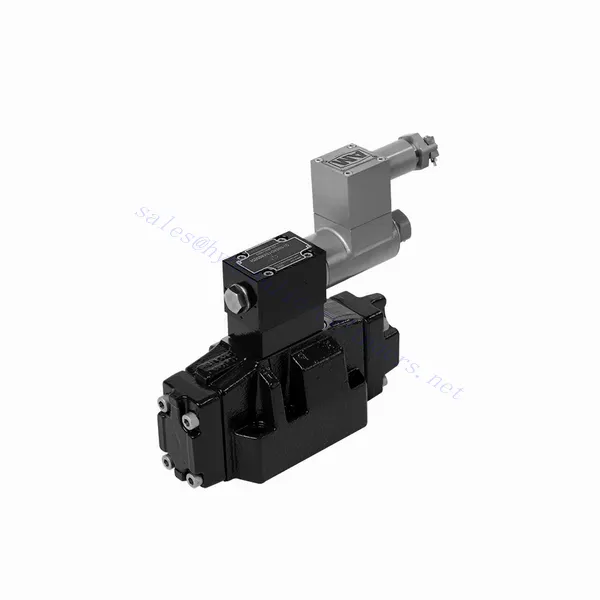
GWEH Series Explosion-proof Directional Hydraulic Valve
En tant que fabricant, fournisseur et exportateur de produits mécaniques, nous proposons des vérins hydrauliques et de nombreux autres produits.
N'hésitez pas à nous contacter pour plus de détails.
Courrier :sales@hydraulic-cylinders.net
Fabricant fournisseur exportateur de vérins hydrauliques.
GWEH Series Explosion-proof Directional Hydraulic Valve
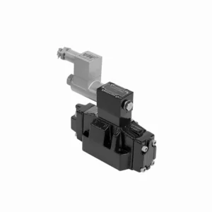
The GWEH series explosion-proof directional hydraulic valve is an innovative solution designed to provide optimal safety and precise control in hydraulic systems operating in hazardous environments. With its explosion-proof features, reliable performance, and advanced functionalities, this valve offers enhanced safety measures, efficient fluid flow control, and compatibility with various industrial applications.
The GWEH series explosion-proof directional hydraulic valve is a reliable and efficient solution for industries operating in hazardous environments. With its explosion-proof design, precise directional control, versatility, and high performance, this valve ensures safety and control in hydraulic systems. Following the recommended usage methods and adhering to regular maintenance practices, the GWEH series valve delivers safe and efficient operation in explosive atmospheres. Upgrade your hydraulic system with the GWEH series explosion-proof directional hydraulic valve and experience enhanced safety, optimal fluid flow control, and reliable performance.
GWEH Series Explosion-proof Directional Hydraulic Valve Key Characteristics:
- Conception antidéflagrante :
- The GWEH series valve is engineered with a robust explosion-proof design, ensuring safe operation in environments containing flammable gases or dust.
- It complies with stringent safety standards and certifications, minimizing the risk of ignition and ensuring the safety of personnel and equipment.
- Contrôle directionnel :
- This hydraulic valve provides precise directional control of fluid flow, allowing for the activation and deactivation of specific hydraulic actuators.
- It enables smooth and reliable operation of various hydraulic functions, such as cylinder extension and retraction or motor direction changes.
- Versatility and Compatibility:
- The GWEH series valve is highly versatile and compatible with various hydraulic systems and applications.
- It can seamlessly integrate into industrial machinery, mobile equipment, and automation systems operating in hazardous environments.
- Haute performance :
- With its advanced design and high-quality construction, the GWEH series hydraulic valve delivers exceptional performance and reliability.
- It ensures consistent and precise control over fluid flow, contributing to efficient and optimized system operation.
GWEH Series Explosion-proof Directional Hydraulic Valve Parameter:
NG10
| Working pressureP,A,B | bar | 315 | |||||||||
| Port T | With external pilot oil drain | bar | 315 | ||||||||
| With internal pilot oil drain | bar | 210 | |||||||||
| Port Y | With external pilot oil drain | bar | 210 | ||||||||
| Pression de contrôle minimale | Avec alimentation externe en huile pilote
Avec alimentation interne en huile pilote (not apply to C, Z, F, G, H, P, T, V) |
bar | 3-position valve 10 | ||||||||
| Spring-return 2-position valve 10 | |||||||||||
| Hydraulic-return 2-position valve 7 | |||||||||||
| Avec alimentation interne en huile pilote ( apply to C, Z, F, G, H, P, T, V) |
bar | 4.5 | |||||||||
| Max. control pressure | bar | 250 | |||||||||
| Fluide | Huile minérale, ester de phosphate | ||||||||||
| Plage de température du fluide | °C | -30 à +80 (Joints NBR) | |||||||||
| -20 à +80 (scellés FKM) | |||||||||||
| Plage de viscosité | mm2/s | 2,8 à 500 | |||||||||
| Controlled quantity in commutating process | cm3 | 3-position valve 2.04 2-position valve 4.08 | |||||||||
| Switching times (= Valve switching time from the neutral position to the switched position)(DC ) | |||||||||||
| Control pressure | bar | 70 | 140 | 210 | 250 | ||||||
| 3-position valve | MS | 65 | 60 | 55 | 50 | ||||||
| 2-position valve | MS | 80 | 75 | 70 | 65 | ||||||
| Temps de commutation (= Temps de commutation de la vanne de la position commutée à la position neutre) | |||||||||||
| 3-position valve | MS | 30 | |||||||||
| 2-position valve | MS | 35 | 40 | 30 | 35 | 25 | 30 | 20 | 25 | ||
| Flow of shortest switching time | L/min | environ 35 | |||||||||
| Position d'installation | HC, HD, HK, HZ and HY of hydraulic return shall be installed horizontally. The rest are arbitrary | ||||||||||
NG16
| Caractéristiques | G-..WEH16../6B2.. type | |||||||
| Working pressureP,A,B bar | 350 | |||||||
| Port T | Avec barre de vidange d'huile pilote externe | 250 | ||||||
| Avec barre de vidange d'huile pilote interne | 210 | |||||||
| Hydraulic-centering 3-position valve With internal pilot oil drain is impossible | ||||||||
| Port Y | Avec barre de vidange d'huile pilote externe | 210 | ||||||
| Pression de contrôle minimale | With external pilot oil supply bar
With internal pilot oil supply bar |
3-position valve 14 | ||||||
| Vanne à rappel par ressort à 2 positions 14 | ||||||||
| Hydraulic-return 2-position valve 14 | ||||||||
| Avec alimentation interne en huile pilote ( apply to C、Z、F、G、H、P、T、V) bar |
When applying back pressure valve or the flow is large, enginery of spool valve is 4.5 bar as C、Z、F、G、H、P、T and V | |||||||
| barre de pression de contrôle maximale | 250 | |||||||
| Fluide | Huile minérale, ester de phosphate | |||||||
| Plage de température du fluide ℃ | -30 à +80 (Joints NBR) | |||||||
| -20 à +80 (scellés FKM) | ||||||||
| Viscosity range mm2 /s 2 | 2,8 à 500 | |||||||
| Volume d'huile pilote commuté | ||||||||
| -Spring-centering 3-position valve cm3 | 5.72 | |||||||
| -2-position valve cm3 | 11.45 | |||||||
| * Temps de commutation (= Temps de commutation de la vanne de la position neutre à la position commutée) (CA et CC) | ||||||||
| Barre de contrôle de pression | 50 | 150 | 250 | |||||
| – Spring-centering 3-position valve ms | 65 | 60 | 58 | |||||
| – 2-position valve ms | 65 | 55 | 50 | |||||
| *Temps de commutation (= Temps de commutation de la vanne de la position neutre à la position commutée) | ||||||||
| – Spring-centering 3-position valve ms | 40 | |||||||
| – 2-position valve ms | 45 | 35 | 30 | |||||
| Position d'installation | C,D,K,Z,Y Type hydraulic-return valves are installed horizontally, the rest can be installed arbitrarily。 | |||||||
| Flow of shorter switching time L/min | environ 35 | |||||||
| Weight of the valve kg | about 10.6 | |||||||
NG25
| Caractéristiques | G-H-…WEH25../6B2… type | |||||||||
| Working pressureP,A,B bar | 350 | |||||||||
| Port T | Avec barre de vidange d'huile pilote externe | 250 | ||||||||
| Avec barre de vidange d'huile pilote interne | 210 | |||||||||
| Hydraulic-centering 3-position valve With internal pilot oil drain is impossible | ||||||||||
| Port Y | Avec barre de vidange d'huile pilote externe | 210 | ||||||||
| Pression de contrôle minimale | With external pilot oil supply bar
With internal pilot oil supply bar |
Spring-centering 3-position valve 13 | ||||||||
| Hydraulic-centering 3-position valve 18 | ||||||||||
| Spring-return 2-position valve 13 | ||||||||||
| Hydraulic-return 2-position valve 18 | ||||||||||
| Avec alimentation interne en huile pilote | When applying back pressure valve or the flow is large, enginery of spool valve is 4.5 bar as C、Z、F、G、H、P、T and V | |||||||||
| barre de pression de contrôle maximale | 250 | |||||||||
| Fluide | Huile minérale, ester de phosphate | |||||||||
| Plage de température du fluide ℃ | -30 à +80 (Joints NBR) | |||||||||
| -20 à +80 (scellés FKM) | ||||||||||
| Viscosity range mm2 /s 2 | 2,8 à 500 | |||||||||
| Volume d'huile pilote commuté | ||||||||||
| -Spring-centering 3-position valve cm3 | 14.2 | |||||||||
| -2-position valve cm3 | 28.4 | |||||||||
| * Temps de commutation (= Temps de commutation de la vanne de la position neutre à la position commutée) (CA et CC) | ||||||||||
| Barre de contrôle de pression | 50 | 140 | 210 | 250 | ||||||
| – Spring-centering 3-position valve ms | 85 | 75 | 70 | 65 | ||||||
| – 2-position valve ms | 160 | 130 | 120 | 105 | ||||||
| **Temps de commutation (= Temps de commutation de la vanne de la position neutre à la position commutée) | ||||||||||
| – Spring-centering 3-position valve ms | 40 | |||||||||
| – 2-position valve ms | 125 | 100 | 90 | 80 | ||||||
| Position d'installation | C,D,K,Z,Y Type hydraulic-return valves are installed horizontally, the rest can be installed arbitrarily。 | |||||||||
| Flow of shorter switching time L/min | environ 35 | |||||||||
| Weight of the valve kg | about 19 | |||||||||
GWEH Series Explosion-proof Directional Hydraulic Valve Advantages:
• Directional valve directional the oil path by controlling the main spool
• Commande électrohydraulique WEH
• Two-position four-way or three-position four-way
• Installation face follows DIN 24340 A, ISO 4401, and CETOP-RP 121H Sub-plate mounting connection
• Remplacer la bobine sans vidanger l'huile
Usage Method Of GWEH Series Explosion-proof Directional Hydraulic Valve :
- Hazardous Area Assessment:
- Conduct a thorough assessment of the hazardous area to identify the specific explosion-proof requirements and classification.
- Determine the appropriate safety measures and precautions needed to comply with the regulations.
- Sélection de la vanne :
- Select the GWEH Series Valve with the suitable specifications, considering factors such as pressure ratings, flow capacity, and voltage requirements.
- Ensure compatibility with the hydraulic system and the specific hazardous environment.
- Installation:
- Follow the manufacturer’s instructions for proper installation of the GWEH Series Valve in the hydraulic system.
- Ensure secure mounting and proper electrical connections, adhering to the recommended torque values and wiring guidelines.
- Control and Activation:
- Utilize the recommended control method, such as electrical signals or remote activation, to operate the GWEH Series Valve.
- Connect the valve to a suitable power source and control system, following the provided wiring diagrams.
How Does A Hydraulic Control Valve Work?
A hydraulic control valve is a critical component in hydraulic systems that regulates the flow and direction of hydraulic fluid to control the operation of hydraulic actuators. It enables precise control over various hydraulic functions, such as extending or retracting cylinders, controlling motor speed and direction, or adjusting the flow rate of hydraulic fluid. Here’s an overview of how a hydraulic control valve works:
- Structure de la vanne :
- A hydraulic control valve typically consists of a valve body, spools or poppets, and various internal passages.
- The valve body contains inlet and outlet ports for fluid connection and chambers that direct the flow.
- The spools or poppets are movable elements within the valve body that control the flow paths and connect the appropriate ports.
- Flow Control:
- The hydraulic control valve regulates the flow of hydraulic fluid by opening and closing specific flow paths within the valve.
- The position of the spools or poppets determines which ports are connected and allows fluid to flow in the desired direction.
- Contrôle directionnel :
- Hydraulic control valves provide directional control by selectively connecting or blocking fluid flow to different hydraulic actuators.
- By adjusting the position of the spools or poppets, the valve determines which actuator receives fluid and in which direction it moves.
- Actuation Methods:
- Hydraulic control valves can be actuated using manual levers, mechanical linkages, solenoids, or pilot pressure control.
- Manual control valves are operated by moving the levers or handles to position the spools or poppets.
- Solenoid-controlled valves use electromagnetic coils to actuate the valve, allowing for remote or automated control.
- Control Modes:
- Hydraulic control valves offer different control modes, such as 2-way, 3-way, or 4-way control.
- A 2-way control valve controls flow in one direction, allowing or blocking fluid flow.
- A 3-way control valve has three ports and can control the flow between two ports while blocking the third.
- A 4-way control valve has four ports and can route fluid between two actuator ports while blocking the other two.
- Compensation de pression :
- Some hydraulic control valves are equipped with pressure compensation features to maintain a consistent flow rate despite changes in system pressure.
- These valves adjust the flow passages based on pressure differentials, allowing for precise control regardless of varying operating conditions.
- Feedback and Control Loops:
- Advanced hydraulic control valves may incorporate feedback mechanisms, such as position or pressure sensors, to provide feedback to a control system.
- This feedback enables closed-loop control, where the system can monitor and adjust the valve’s position or flow based on desired setpoints or operating conditions.
Capacité de l'usine :
(1) Assemblage
Nous disposons d'une plateforme d'assemblage indépendante de recherche et développement de premier ordre. Notre atelier de production de vérins hydrauliques dispose de quatre lignes d'assemblage semi-automatiques de vérins de levage et d'une ligne d'assemblage automatique de vérins d'inclinaison, pour une capacité de production annuelle prévue d'un million de pièces. L'atelier de vérins spéciaux est équipé d'un système d'assemblage de nettoyage semi-automatique de diverses spécifications, d'une capacité de production annuelle prévue de 200 000 pièces et dispose d'équipements d'usinage CNC de pointe, d'un centre d'usinage, d'équipements spéciaux d'usinage de haute précision, d'une machine de soudage robotisée, d'une machine de nettoyage automatique, d'une machine d'assemblage automatique de vérins et d'une ligne de peinture automatique. Nous disposons de plus de 300 équipements critiques. L'allocation optimale et l'utilisation efficace des ressources garantissent la précision et la qualité des produits.


(2) Usinage
L'atelier d'usinage est équipé d'un centre de tournage sur rail incliné personnalisé, d'un centre d'usinage, d'une machine à honer à grande vitesse, d'un robot de soudage et d'autres équipements connexes, qui peuvent traiter des tubes cylindriques d'un diamètre intérieur maximal de 400 mm et d'une longueur maximale de 6 mètres.

(3) Soudage

(4) Peinture et revêtement
Avec des lignes de revêtement de peinture à base d'eau automatiques à cylindre de petite et moyenne taille, pour réaliser le chargement et le déchargement automatiques par robot et la pulvérisation automatique, la capacité de conception est de 4 000 pièces par équipe ;
Nous disposons également d'une ligne de production de peinture semi-automatique pour gros cylindres, alimentée par une chaîne de traction, d'une capacité de conception de 60 caisses par équipe.


(5) Essais
Nous disposons d'installations d'inspection et de bancs d'essai de premier ordre pour garantir que les performances de la bouteille sont conformes aux exigences.

Nous sommes l'un des meilleurs fabricants de vérins hydrauliques. Nous proposons une gamme complète de vérins hydrauliques. Nous fournissons également les vérins correspondants. boîtes de vitesses agricolesNous exportons nos produits dans le monde entier et nous avons acquis une excellente réputation grâce à la qualité supérieure de nos produits et à notre service après-vente. Nous invitons nos clients, nationaux et internationaux, à nous contacter pour négocier, échanger des informations et… coopérer avec nous!
Vérin hydraulique Application :
