
KSE66-C0820 Solenoid Directional Valve
En tant que fabricant, fournisseur et exportateur de produits mécaniques, nous proposons des vérins hydrauliques et de nombreux autres produits.
N'hésitez pas à nous contacter pour plus de détails.
Courrier :sales@hydraulic-cylinders.net
Fabricant fournisseur exportateur de vérins hydrauliques.
KSE66-C0820 Solenoid Directional Valve
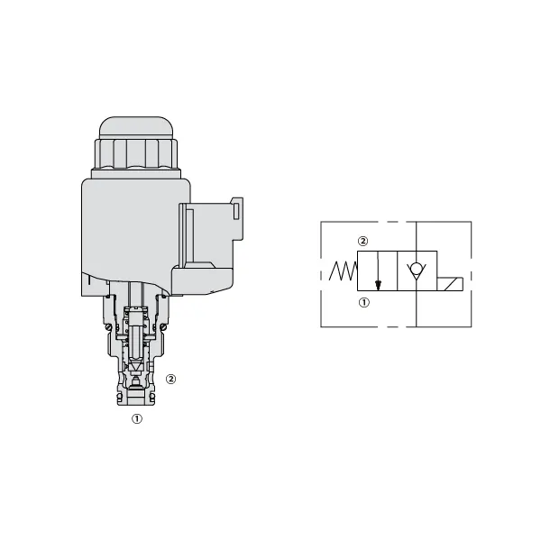
The kse66-c0820 solenoid directional valve is an innovative and reliable component designed to elevate fluid control systems to new heights. With its advanced features and precise control capabilities, this valve is the perfect solution for various industrial applications. Whether in manufacturing, automation, or other fluid control processes, the kse66-c0820 solenoid directional valve ensures seamless operation and exceptional performance.
The KSE66-C0820 Solenoid Directional Valve offers exceptional fluid control capabilities, ensuring optimal performance in various industrial applications. With its high-quality construction, precise control, compact design, and rapid response time, this valve is a reliable choice for streamlining fluid control systems. By following the correct usage method and implementing regular maintenance practices, you can maximize the potential of the KSE66-C0820 Solenoid Directional Valve and achieve superior fluid control efficiency in your operations. Upgrade your fluid control system today with the reliability and performance of the KSE66-C0820 Solenoid Directional Valve.
KSE66-C0820 Solenoid Directional Valve Characteristics:
- Construction de haute qualité : The KSE66-C0820 Solenoid Directional Valve is built with top-notch materials, ensuring exceptional durability and long-lasting performance. It is designed to withstand demanding operating conditions, including high pressures and harsh environments, without compromising its functionality.
- Precise Fluid Control: With its cutting-edge design, the KSE66-C0820 Solenoid Directional Valve offers precise control over fluid flow and direction. It enables accurate adjustments, allowing for optimal performance and efficiency in various applications.
- Compact and Lightweight: This valve is engineered to be compact and lightweight, making it easy to integrate into different fluid control systems. Its streamlined design ensures efficient use of space while maintaining excellent performance.
- Temps de réponse rapide : The KSE66-C0820 Solenoid Directional Valve boasts a rapid response time, providing quick and reliable switching between different flow paths. This ensures smooth operation and enhances system performance, even in dynamic and time-sensitive applications.
KSE66-C0820 Solenoid Directional Valve Parameter:
| Pression nominale | 350 bar(5000 psi) |
| Débit de pointe | 40 L/min(10 gpm) |
| Fluide | Mineral oil - Suitable for Buna N or Fluorocarbon seals |
| Phosphate ester - Suitable for Fluorocarbon seals | |
| Plage de température du fluide ℃ | – 30 to 80(Buna N seals) |
| – 20 to 80(Fluorocarbon seals) | |
| Plage de viscosité | 7,4 à 420 mm2/s |
| Degree of fluid contamination | Le niveau de pollution minimal est conforme à la norme ISO 4406, niveau 18/16/13 ; le niveau 15/13/11 est recommandé pour prolonger la durée de vie. |
| Internal leakage | ≦ 5 d/min |
| Cavité | VC08-2 |
| Poids | 0.33 kg |
| Coil duty rating | Continu de 85% à 115% de tension nominale |
| Initial coil current draw at 20℃ | 1.5A at 12VDC; 0.8A at 24VDC |
| Tension d'appel minimale | 85% of nominal at 350bar |
KSE66-C0820 Solenoid Directional Valve Advantages:
• Bobine nominale à service continu
• Les cartouches sont interchangeables en termes de tension
• Bobines électroniques étanches en option classées IP69K
• Cavité commune industrielle
• Pièces trempées pour une longue durée de vie
Usage Method Of KSE66-C0820 Solenoid Directional Valve:
- Évaluation du système : Assess the fluid control system requirements, including pressure ratings, flow rates, and directional control needs. Ensure that the KSE66-C0820 Solenoid Directional Valve is compatible with your specific application.
- Montage et connexion : Select the appropriate mounting method based on your system configuration and available space. Install the valve securely, aligning it with the fluid lines. Connect the valve using compatible fittings and connectors, ensuring tight and leak-free connections.
- Connexion électrique : Connect the solenoid of the valve to the appropriate power supply following the manufacturer’s guidelines. Ensure correct wiring and observe safety precautions during the electrical connection process.
- Testing and Calibration: Gradually introduce fluid flow into the system and monitor the valve’s performance. Test different operating conditions, such as pressure and flow variations, and calibrate the valve settings as needed to achieve optimal control and system functionality.
How To Replace Valve Cartridge Delta Faucet?
To replace the valve cartridge in a Delta faucet, follow these step-by-step instructions:
- Rassemblez les outils nécessaires : You will need a set of Allen wrenches, a pair of pliers (adjustable or groove-joint), a screwdriver (Phillips or flathead), and a replacement Delta valve cartridge specific to your faucet model.
- Turn off the water supply: Locate the shutoff valves under the sink or at the main water supply line and turn off the water supply to the faucet. Open the faucet handles to release any remaining water in the lines and ensure the water is completely off.
- Dismantle the faucet handle: Delta faucets have different handle styles, such as single lever or double handle. For a single lever handle, locate the set screw on the handle, usually located under a decorative cap or button. Use an Allen wrench to remove the set screw and pull off the handle. For a double handle faucet, remove the handle by unscrewing the decorative cap or handle screw.
- Remove the cartridge: Once the handle is removed, you will see the cartridge. Use pliers to loosen and remove the cartridge nut by turning it counterclockwise. If it is stubborn, you can use a cartridge removal tool for added leverage. Pull the cartridge straight out of the faucet body.
- Install the replacement cartridge: Take the new Delta valve cartridge and align it with the faucet body, ensuring any tabs or notches match up correctly. Gently push the cartridge into the faucet body until it fits snugly.
- Reassemble the faucet: Once the new cartridge is installed, reassemble the faucet in the reverse order. Slide the cartridge nut back onto the valve body and tighten it with pliers. Make sure it is securely fastened but avoid over-tightening. Reattach the faucet handle and tighten the set screw or handle screw.
- Turn on the water supply: Slowly turn the water supply back on using the shutoff valves or the main water supply. Check for any leaks around the faucet and handle. If there are leaks, tighten the cartridge nut or handle further as needed.
- Test the faucet: With the water supply restored, test the faucet by turning on the handles and checking for smooth operation. Make sure hot and cold water flows correctly and adjust the temperature as desired.
Capacité de l'usine :
(1) Assemblage
Nous disposons d'une plateforme d'assemblage indépendante de recherche et développement de premier ordre. Notre atelier de production de vérins hydrauliques dispose de quatre lignes d'assemblage semi-automatiques de vérins de levage et d'une ligne d'assemblage automatique de vérins d'inclinaison, pour une capacité de production annuelle prévue d'un million de pièces. L'atelier de vérins spéciaux est équipé d'un système d'assemblage de nettoyage semi-automatique de diverses spécifications, d'une capacité de production annuelle prévue de 200 000 pièces et dispose d'équipements d'usinage CNC de pointe, d'un centre d'usinage, d'équipements spéciaux d'usinage de haute précision, d'une machine de soudage robotisée, d'une machine de nettoyage automatique, d'une machine d'assemblage automatique de vérins et d'une ligne de peinture automatique. Nous disposons de plus de 300 équipements critiques. L'allocation optimale et l'utilisation efficace des ressources garantissent la précision et la qualité des produits.


(2) Usinage
L'atelier d'usinage est équipé d'un centre de tournage sur rail incliné personnalisé, d'un centre d'usinage, d'une machine à honer à grande vitesse, d'un robot de soudage et d'autres équipements connexes, qui peuvent traiter des tubes cylindriques d'un diamètre intérieur maximal de 400 mm et d'une longueur maximale de 6 mètres.

(3) Soudage

(4) Peinture et revêtement
Avec des lignes de revêtement de peinture à base d'eau automatiques à cylindre de petite et moyenne taille, pour réaliser le chargement et le déchargement automatiques par robot et la pulvérisation automatique, la capacité de conception est de 4 000 pièces par équipe ;
Nous disposons également d'une ligne de production de peinture semi-automatique pour gros cylindres, alimentée par une chaîne de traction, d'une capacité de conception de 60 caisses par équipe.


(5) Essais
Nous disposons d'installations d'inspection et de bancs d'essai de premier ordre pour garantir que les performances de la bouteille sont conformes aux exigences.

Nous sommes l'un des meilleurs fabricants de vérins hydrauliques. Nous proposons une gamme complète de vérins hydrauliques. Nous fournissons également les vérins correspondants. boîtes de vitesses agricolesNous exportons nos produits dans le monde entier et nous avons acquis une excellente réputation grâce à la qualité supérieure de nos produits et à notre service après-vente. Nous invitons nos clients, nationaux et internationaux, à nous contacter pour négocier, échanger des informations et… coopérer avec nous!
Vérin hydraulique Application :
