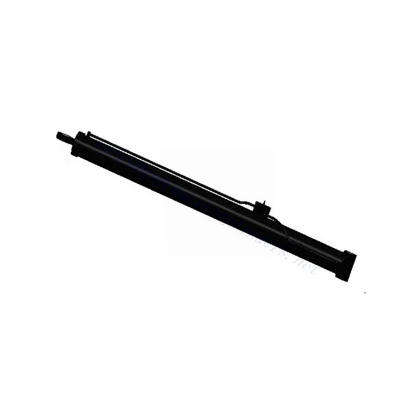
Cylindre de relevage pour grue mobile
En tant que fabricant, fournisseur et exportateur de produits mécaniques, nous proposons des vérins hydrauliques et de nombreux autres produits.
N'hésitez pas à nous contacter pour plus de détails.
Courrier :sales@hydraulic-cylinders.net
Fabricant fournisseur exportateur de vérins hydrauliques.
Cylindre de relevage pour grue mobile
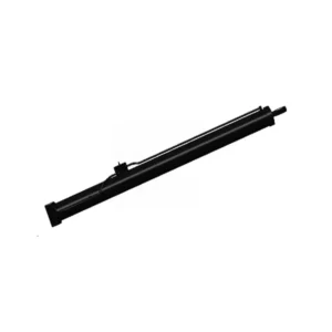
The mobile crane luffing cylinder is essential in mobile crane systems and is designed to enhance these powerful machines’ vertical reach and lifting efficiency. This hydraulic cylinder plays a crucial role in adjusting the angle of the crane’s boom, allowing operators to extend or retract the boom smoothly and precisely.
The mobile crane luffing cylinder is vital for enhancing the vertical reach, lifting efficiency, and overall performance of mobile cranes. With its robust construction, precise angle adjustment, extended vertical space, and improved lifting capacity, this hydraulic cylinder empowers operators to navigate challenging construction sites and industrial environments with ease and safety. By following the recommended usage methods and maintenance practices, operators can maximize the longevity and performance of the mobile crane luffing cylinder, contributing to increased productivity, efficiency, and operator confidence in completing various lifting tasks. Invest in this essential hydraulic component to elevate the capabilities of your mobile crane, ensuring successful and efficient operations in diverse construction and industrial applications.
Mobile Crane Luffing Cylinder Key Characteristics:
- Construction robuste :
- The mobile crane luffing cylinder is built with high-quality materials, ensuring durability, strength, and resistance to heavy loads and harsh environmental conditions.
- It is designed to withstand the rigors of demanding construction sites and maintain optimal performance over extended periods.
- Precise Angle Adjustment:
- This hydraulic cylinder enables precise angle adjustment of the crane’s boom, providing operators with fine control over vertical reach and positioning.
- It offers smooth and responsive movement, allowing for accurate load placement and minimizing the risk of collisions or accidents.
- Extended Vertical Reach:
- The mobile crane luffing cylinder extends the crane’s vertical reach by adjusting the angle of the boom.
- It enhances the crane’s flexibility in accessing elevated work areas, such as high-rise construction sites or industrial installations.
- Lifting Efficiency:
- By optimizing the angle of the boom, the luffing cylinder enhances the lifting efficiency of the mobile crane.
- It allows for better load distribution, reducing stress on the crane’s components and improving overall lifting capacity.
Mobile Crane Luffing Cylinder Parameter:
| Nom du produit | Cylindre de relevage pour grue mobile |
| Caractéristiques: | Realizing the up-and-down pitching rotation of the boom is the main driving force for lifting |
| Diamètre d'alésage : | 100mm~560mm |
| Diamètre de la tige : | 50mm~480mm Stroke≤5000 mm |
| Pression: | Maximum 36MPa |
| Luffing Cylinder Applications: | Grue mobile |
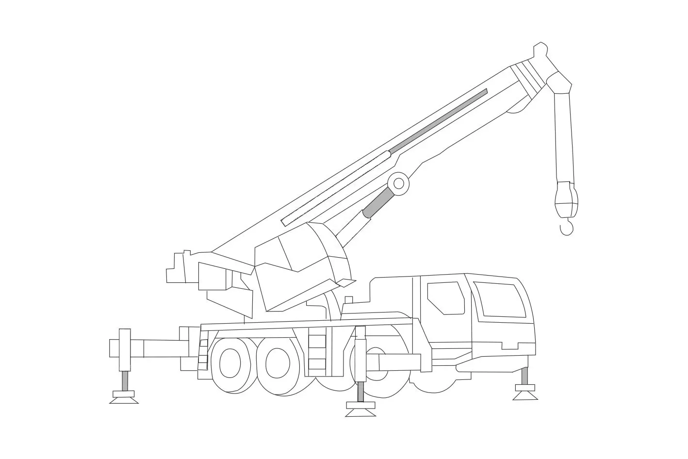
Diagramme d'identification de la grue mobile :
Usage Method Of Mobile Crane Luffing Cylinder:
- Précautions de sécurité :
- Before operating the mobile crane, ensure all safety guidelines and regulations are followed.
- Conduct a thorough inspection of the crane and its components, including the luffing cylinder, to ensure they are in proper working condition.
- Familiarize with Controls:
- Understand the control mechanisms and operating procedures specific to your mobile crane model.
- Identify the control for adjusting the luffing angle and ensure it functions properly.
- Luffing Angle Adjustment:
- Activate the control for the luffing cylinder, typically located in the operator’s cabin.
- Use the control to extend or retract the boom, adjusting the luffing angle as required for the lifting operation.
- Follow the load charts and manufacturer’s guidelines for the appropriate luffing angles based on the load weight and radius.
- Load Placement and Monitoring:
- Once the desired luffing angle is achieved, carefully position the load using the crane’s other controls, such as the hoist and swing mechanisms.
- Continuously monitor the load and adjust the luffing angle to maintain stability and safety during the lifting operation.
Comment relâcher la pression sur le système hydraulique ?
Releasing pressure from a hydraulic system is a necessary safety procedure that should be followed whenever maintenance or repair work is performed. Here are the general steps to release pressure from a hydraulic system:
- Identifier la source d’alimentation :
- Determine the power source supplying pressure to the hydraulic system, such as an electric motor, an engine-driven pump, or a manual pump.
- Locate the power switch or control valve associated with the power source.
- Coupez l'alimentation électrique :
- Turn off the power switch or control valve to stop the power source from supplying pressure to the hydraulic system.
- If an engine powers the hydraulic system, shut off the engine completely.
- Engage the System Controls:
- Operate the control valves or switches on the hydraulic system to move actuators or components to neutral or resting positions.
- This step helps relieve residual pressure and allows the hydraulic fluid to flow back to the reservoir.
- Release Pressure at the Pump:
- If the hydraulic system has a pump with a pressure relief valve, locate the valve.
- Turn the pressure relief valve counterclockwise (or as specified by the manufacturer) to release pressure gradually.
- If available, check the system pressure gauge to ensure that pressure is relieved.
- Bleed Air from the System:
- Some hydraulic systems may have air trapped within the system, which can cause pressure buildup.
- To release air, open the air bleed valves or loosen fittings strategically to allow air to escape.
- Start from the lowest points in the system and work your way up to the highest points.
- Keep bleeding the system until a steady flow of hydraulic fluid is observed without air bubbles.
- Vérifier la libération de pression :
- Check the pressure gauge, if available, to ensure that the pressure has been fully released.
- Double-check the system controls to ensure that all actuators and components are neutral or resting.
Capacité de l'usine :
(1) Assemblage
Nous disposons d'une plateforme d'assemblage indépendante de recherche et développement de premier ordre. Notre atelier de production de vérins hydrauliques dispose de quatre lignes d'assemblage semi-automatiques de vérins de levage et d'une ligne d'assemblage automatique de vérins d'inclinaison, pour une capacité de production annuelle prévue d'un million de pièces. L'atelier de vérins spéciaux est équipé d'un système d'assemblage de nettoyage semi-automatique de diverses spécifications, d'une capacité de production annuelle prévue de 200 000 pièces et dispose d'équipements d'usinage CNC de pointe, d'un centre d'usinage, d'équipements spéciaux d'usinage de haute précision, d'une machine de soudage robotisée, d'une machine de nettoyage automatique, d'une machine d'assemblage automatique de vérins et d'une ligne de peinture automatique. Nous disposons de plus de 300 équipements critiques. L'allocation optimale et l'utilisation efficace des ressources garantissent la précision et la qualité des produits.


(2) Usinage
L'atelier d'usinage est équipé d'un centre de tournage sur rail incliné personnalisé, d'un centre d'usinage, d'une machine à honer à grande vitesse, d'un robot de soudage et d'autres équipements connexes, qui peuvent traiter des tubes cylindriques d'un diamètre intérieur maximal de 400 mm et d'une longueur maximale de 6 mètres.

(3) Soudage

(4) Peinture et revêtement
Avec des lignes de revêtement de peinture à base d'eau automatiques à cylindre de petite et moyenne taille, pour réaliser le chargement et le déchargement automatiques par robot et la pulvérisation automatique, la capacité de conception est de 4 000 pièces par équipe ;
Nous disposons également d'une ligne de production de peinture semi-automatique pour gros cylindres, alimentée par une chaîne de traction, d'une capacité de conception de 60 caisses par équipe.


(5) Essais
Nous disposons d'installations d'inspection et de bancs d'essai de premier ordre pour garantir que les performances de la bouteille sont conformes aux exigences.

Nous sommes l'un des meilleurs fabricants de vérins hydrauliques. Nous proposons une gamme complète de vérins hydrauliques. Nous fournissons également les vérins correspondants. boîtes de vitesses agricolesNous exportons nos produits dans le monde entier et nous avons acquis une excellente réputation grâce à la qualité supérieure de nos produits et à notre service après-vente. Nous invitons nos clients, nationaux et internationaux, à nous contacter pour négocier, échanger des informations et… coopérer avec nous!
Vérin hydraulique Application :
