4WRPEH Series Proportional Directional Hydraulic Valve
4WRPEH Series Proportional Directional Hydraulic Valve
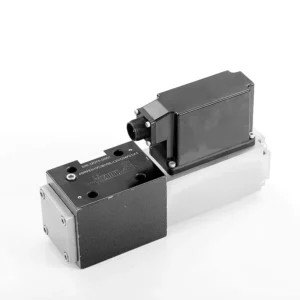
The 4WRPEH series proportional directional hydraulic valve is an advanced hydraulic component designed to deliver exceptional precision and control in hydraulic systems. With its innovative proportional directional control technology, this valve enables accurate flow regulation and smooth directional changes.
The 4WRPEH series proportional directional hydraulic valve empowers hydraulic systems with precise flow control, versatile functionality, and enhanced efficiency. Its proportional directional control technology ensures accurate and responsive flow adjustment, while the high flow capacity guarantees reliable performance even in demanding applications. By following the recommended usage methods and maintenance guidelines, you can maximize the benefits and longevity of the 4WRPEH series valve, elevating your hydraulic system to new levels of precision and control. Upgrade your hydraulic setup today and experience the power of the 4WRPEH series proportional directional hydraulic valve.
4WRPEH Series Proportional Directional Hydraulic Valve Key Characteristics:
- Kontrol Arah Proporsional:
- The 4WRPEH series valve utilizes state-of-the-art proportional directional control technology, allowing precise and proportional flow adjustment based on control signals.
- This feature ensures accurate and responsive control, resulting in improved system performance, reduced energy consumption, and enhanced productivity.
- Fungsionalitas Serbaguna:
- This valve offers versatile control over hydraulic fluid direction, making it suitable for a wide range of applications.
- It enables seamless activation and deactivation of hydraulic components such as cylinders, motors, and actuators in different directions, enhancing system flexibility and adaptability.
- Kapasitas Aliran Tinggi:
- The 4WRPEH series valve is engineered to handle high flow rates, making it ideal for applications that require substantial hydraulic power.
- Its robust construction ensures reliable performance even under demanding conditions, providing consistent and efficient flow control.
- Precise Metering:
- With its proportional control technology, this valve offers precise metering of hydraulic fluid, allowing for accurate control and regulation of flow rates.
- This precision enhances overall system performance and ensures precise movements of hydraulic actuators.
4WRPEH Series Proportional Directional Hydraulic Valve Parameter:
NG6
| Umum | |||||||
| Desain | Katup spool, dioperasikan langsung, dengan selongsong baja. | ||||||
| Aktuasi | Solenoid proporsional dengan kontrol posisi, OBE | ||||||
| Jenis koneksi | Pemasangan pelat dasar, pola porting sesuai dengan ISO 4401-03-02-0-05 | ||||||
| Posisi pemasangan | Setiap | ||||||
| Kisaran suhu sekitar | ℃ | -20…+50 | |||||
| Berat | kg | sekitar 2,75 | |||||
| Ketahanan getaran maksimum (kondisi pengujian) | Maks. 25 g, uji getaran ruang angkasa ke segala arah (24 jam) | ||||||
| Hidrolik (diukur pada p=100 bar, dengan HLP46 pada ϑoil = 40℃ ±5℃) | |||||||
| Fluida bertekanan | Minyak mineral (HL, HLP) sesuai DIN 51 524 | ||||||
| Kisaran viskositas | direkomendasikan | mm²/detik | 20…100 | ||||
| maks. yang diizinkan | mm²/detik | 10…800 | |||||
| Kisaran suhu fluida tekanan | ℃ | -20 hingga +70 | |||||
| Tingkat kontaminasi maksimum yang diizinkan dari cairan bertekanan Kelas kemurnian menurut ISO 4406 (c) | Kelas 18/16/13 | ||||||
| Aliran nominal (Δp = 35 bar per sisi) | L/menit | 2 | 4 | 12 | 24 | 40 | |
| Tekanan operasi maks. | batang | Pelabuhan A, B, P: 315 | |||||
| Tekanan maksimum | batang | Pelabuhan T: 250 | |||||
| Aliran kebocoran pada 100 bar | Linier | cm³/menit | <150 | <180 | <300 | <500 | <900; |
| Nonlinier | cm³/menit | / | / | / | <300 | <450; | |
| Statis/Dinamis | |||||||
| Histeresis | % | ≤0,2 | |||||
| Waktu aktivasi untuk langkah sinyal 0 … 100% | MS | 10 | |||||
| Pergeseran suhu | Pergeseran nol < 1% pada ΔT=40℃ | ||||||
| Tidak ada kompensasi sama sekali | Dari pabrik ±1% | ||||||
| Elektronik kontrol listrik terintegrasi dalam katup. | |||||||
| Siklus kerja relatif | % | 100ED | |||||
| Tingkat perlindungan | IP65 | ||||||
| Koneksi | Konektor plug-in 6P+PE, DIN 43563 | ||||||
| Tegangan suplai Terminal A Terminal B |
24VDCnom | ||||||
| min. 21VDC / maks. 40VDC | |||||||
| 0V (riak maks. 2) | |||||||
| Perlindungan sekering, eksternal | AF | 2.5 | |||||
| input, versi “A1” Terminal D (UE) Terminal E |
Penguat diferensial, Ri = 100 kΩ | ||||||
| 0…±10V | |||||||
| 0V | |||||||
| Input, versi “F1” Terminal D (ID-E) Terminal E (ID-E) |
Muat, Rsh = 200 Ω | ||||||
| 4…12…20mA | |||||||
| Loop arus IDE kembali | |||||||
| Sinyal uji, versi “A1” Terminal F (Tes U) Terminal C |
LVDT | ||||||
| 0…±10V | |||||||
| Referensi 0 V | |||||||
| Sinyal uji, versi “F1” Terminal F ( I FC ) Terminal C ( I FC ) |
Sinyal LVDT 4 … (12) … 20 mA pada beban eksternal 200 … 500 Ω maksimum | ||||||
| 4 … (12) … 20mA (keluaran) | |||||||
| Loop arus IFC kembali | |||||||
| Pengaturan | Dikaliibrasi sebelum pengiriman, lihat kurva karakteristik. | ||||||
NG10
| Umum | |||||
| Desain | Katup spool, dioperasikan langsung, dengan selongsong baja. | ||||
| Aktuasi | Solenoid proporsional dengan kontrol posisi, OBE | ||||
| Jenis koneksi | Port pelat, pola porting (ISO 4401-05-04-0-05) | ||||
| Posisi pemasangan | Setiap | ||||
| Kisaran suhu keadaan | ℃ | -20…+50 | |||
| Berat | kg | sekitar 7.1 | |||
| Ketahanan getaran maksimum (kondisi pengujian) | Maks. 25 g, uji getaran ruang angkasa ke segala arah (24 jam) | ||||
| Hidraulik (diukur dengan HLP 46, ϑoil =40℃ ±5℃) | |||||
| Fluida bertekanan | Oli hidrolik sesuai dengan DIN 51524…535 | ||||
| Kisaran viskositas | direkomendasikan | mm²/detik | 20…100 | ||
| Maksimum yang diizinkan | mm²/detik | 10…800 | |||
| Kisaran suhu fluida tekanan | ℃ | -20 hingga +70 | |||
| Tingkat kontaminasi maksimum yang diizinkan pada cairan hidrolik, kelas kebersihan menurut ISO 4406 (c) | Kelas 18/16/13 | ||||
| Aliran nominal (Δp = 35 bar per sisi) | L/menit | 50 | 100 | ||
| Tekanan operasi maks. | batang | Port PAB: 315 | |||
| Tekanan maksimum | batang | Pelabuhan T: 250 | |||
| Aliran kebocoran pada 100 bar | Linier | cm³/menit | <1200 | <1500 | |
| Nonlinier | cm³/menit | <600 | <600 | ||
| Statis/Dinamis | |||||
| Histeresis | % | ≤0,2 | |||
| Waktu aktivasi untuk langkah sinyal 0 … 100% | MS | 25 | |||
| Pergeseran suhu | Pergeseran nol < 1% pada ΔT=40℃ | ||||
| Tidak ada kompensasi sama sekali | Dari pabrik ±1% | ||||
| Elektronik kontrol listrik terintegrasi dalam katup. | |||||
| Siklus kerja relatif | % | 100ED | |||
| Tingkat perlindungan | IP65 (dengan konektor penghubung terpasang dan terkunci) | ||||
| Koneksi | Konektor kawin 6P+PE, DIN 43563 | ||||
| Tegangan suplai Terminal A Terminal B |
24VDCnom | ||||
| min. 21VDC / maks. 40VDC | |||||
| Riak maksimum 2 VDC | |||||
| Perlindungan sekering, eksternal | AF | 2.5 | |||
| Masukan, versi “A1” Terminal D (UE) Terminal E |
Penguat diferensial, Ri = 100 kΩ | ||||
| 0…±10V | |||||
| 0V | |||||
| Input, versi “F1” Terminal D (IDE) Terminal E (IDE) |
Muat, Rsh = 200 | ||||
| 4…12…20mA | |||||
| Loop arus IDE kembali | |||||
| Sinyal uji, versi “A1” Terminal F (UTes) Terminal C |
LVDT | ||||
| 0…±10V | |||||
| Referensi 0 V | |||||
| Sinyal uji, versi “F1” Terminal F ( I FC ) Terminal C ( I FC ) |
LVDT | ||||
| Keluaran 4…20 mA | |||||
| Loop arus IFC masukan | |||||
4WRPEH Series Proportional Directional Hydraulic Valve Advantages:
• Katup solenoid servo kerja langsung dengan piston kontrol dan selongsong katup, dengan kinerja servo
• Single-side drive, optional with power-off safety function
Solenoid kontrol dengan umpan balik bawaan dan papan penguat terintegrasi (OBE), pengaturan pabrik.
• Koneksi listrik penguat diferensial input sinyal 6P+PE dengan antarmuka, input opsional A1: ±10V, atau antarmuka F1: 4…20mA (Rsh =200Ω)
• Panel mounting, the mounting surface complies with ISO 4401-03-02
Usage Method Of 4WRPEH Series Proportional Directional Hydraulic Valve :
- Evaluasi Sistem:
- Evaluate your hydraulic system and identify the specific flow and directional control requirements.
- Determine if the 4WRPEH series valve is suitable based on its flow capacity, pressure rating, and compatibility with your system.
- Pemilihan Katup:
- Select the appropriate variant of the 4WRPEH series valve based on your system parameters, flow requirements, and directional control needs.
- Consider factors such as maximum flow rate, pressure rating, response time, and operational conditions.
- Instalasi:
- Follow the manufacturer’s installation instructions carefully, ensuring proper alignment and secure mounting of the valve.
- Make leak-free connections and ensure correct flow direction alignment to guarantee optimal performance.
- Control Signal Connection:
- Hubungkan kabel sinyal kontrol katup ke perangkat kontrol yang sesuai, seperti penguat proporsional atau unit kontrol elektronik.
- Ensure proper wiring and compatibility between the valve and the control device for accurate and responsive control.
How To Hook Two Hydraulic Valves Together?
Hooking two hydraulic valves together requires careful consideration of the valve types, their functions, and the specific hydraulic system requirements. Here are general guidelines on how to hook two hydraulic valves together:
- Identify Valve Types:
- Determine the types of valves you are working with, such as directional control valves, pressure control valves, flow control valves, or any other specific valves required for your system.
- Ensure that both valves are compatible in terms of size, pressure ratings, flow capacity, and function.
- Understand Valve Functions:
- Familiarize yourself with the functions of each valve. For example, directional control valves regulate fluid flow direction, pressure control valves control system pressure, and flow control valves manage flow rates.
- Determine how the combination of these valves will contribute to achieving the desired hydraulic system operation.
- Determine Valve Placement:
- Decide where in the hydraulic system you want to install the two valves. Consider factors such as fluid flow path, pressure requirements, and the desired control sequence.
- Ensure that the valve placement allows for proper fluid flow and accessibility for maintenance and operation.
- Connect Valve Ports:
- Identify the inlet and outlet ports of each valve. These ports may be labeled or indicated in the valve documentation.
- Use appropriate hydraulic fittings, adapters, or connectors to connect the ports of the two valves together.
- Ensure a secure and leak-free connection by using suitable sealing materials, such as O-rings or thread sealants.
- Consider Valve Interactions:
- Evaluate how the interaction between the two valves will affect the hydraulic system’s overall performance.
- Ensure that the combined operation of the valves does not create conflicts or result in unintended consequences, such as pressure spikes, flow restrictions, or unintended movements.
- Integrasi Sinyal Kontrol:
- If the valves require control signals, such as electrical or pneumatic signals, determine how these signals will be integrated.
- Connect the control signal lines of both valves to the appropriate control devices, such as hydraulic control modules, electronic control units, or manual control levers.
- Ensure proper wiring, compatibility, and synchronization between the control devices and the valves to achieve the desired control and coordination.
- Test and Adjust:
- After hooking the valves together, thoroughly test the hydraulic system to ensure proper operation.
- Monitor the system for any issues, such as leaks, excessive pressure drops, or unexpected behavior.
- Make necessary adjustments, such as fine-tuning control settings or modifying valve placement if required.
Kemampuan & Kapasitas Pabrik:
(1) Perakitan
Kami memiliki platform perakitan penelitian dan pengembangan independen kelas satu. Bengkel produksi silinder hidrolik memiliki empat jalur perakitan silinder pengangkat semi-otomatis dan satu jalur perakitan silinder kemiringan otomatis, dengan kapasitas produksi tahunan yang dirancang sebesar 1 juta keping. Bengkel silinder khusus dilengkapi dengan berbagai spesifikasi sistem perakitan pembersihan semi-otomatis dengan kapasitas produksi tahunan yang dirancang sebesar 200.000 dan dilengkapi dengan peralatan permesinan CNC yang terkenal, pusat permesinan, peralatan khusus pemrosesan silinder presisi tinggi, mesin las robot, mesin pembersih otomatis, mesin perakitan silinder otomatis, dan jalur produksi pengecatan otomatis. Peralatan penting yang ada lebih dari 300 set (set). Alokasi optimal dan penggunaan sumber daya peralatan yang efisien memastikan persyaratan akurasi produk dan memenuhi kebutuhan produk berkualitas tinggi.


(2) Pemesinan
Bengkel permesinan dilengkapi dengan pusat pembubutan rel miring yang disesuaikan, pusat permesinan, mesin pengasah berkecepatan tinggi, robot pengelasan, dan peralatan terkait lainnya, yang dapat menangani pemrosesan tabung silinder dengan diameter bagian dalam maksimum 400mm dan panjang maksimum 6 meter.

(3) Pengelasan

(4) Pengecatan & pelapisan
Dengan jalur pelapisan cat berbasis air otomatis silinder kecil dan menengah, untuk mencapai bongkar muat robot otomatis dan penyemprotan otomatis, kapasitas desain 4000 buah per shift;
Kami juga memiliki lini produksi cat semi-otomatis untuk silinder besar yang ditenagai oleh rantai daya, dengan kapasitas desain 60 kasus per shift.


(5) Pengujian
Kami memiliki fasilitas inspeksi kelas satu dan test bed untuk memastikan bahwa kinerja silinder memenuhi persyaratan.

Kami adalah salah satu produsen silinder hidrolik terbaik. Kami dapat menawarkan silinder hidrolik yang lengkap. Kami juga menyediakan produk yang sesuai. gearbox pertanian. Kami telah mengekspor produk kami ke klien di seluruh dunia dan mendapatkan reputasi yang baik karena kualitas produk dan layanan purna jual kami yang unggul. Kami menyambut pelanggan di dalam dan luar negeri untuk menghubungi kami untuk menegosiasikan bisnis, bertukar informasi, dan bekerja sama dengan kami!