


Katup Hidrolik Kontrol Aliran Seri Z2FRM
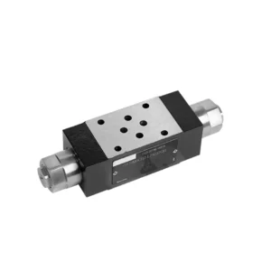

Katup hidrolik pengontrol aliran seri Z2FRM adalah komponen hidrolik canggih yang dirancang untuk merevolusi kontrol dan efisiensi sistem hidrolik. Dengan fitur-fitur canggih dan kinerja yang luar biasa, katup ini memberikan kontrol aliran yang presisi dan meningkatkan produktivitas keseluruhan mesin hidrolik.
Katup hidrolik pengontrol aliran seri Z2FRM adalah solusi inovatif untuk kontrol aliran yang presisi dalam sistem hidrolik. Dengan presisi, fleksibilitas, dan daya tahan yang tak tertandingi, katup ini memungkinkan operator untuk mengoptimalkan kinerja dan efisiensi mesin hidrolik mereka. Dengan mengikuti metode penggunaan dan panduan perawatan yang direkomendasikan, Anda dapat membuka potensi penuh katup hidrolik pengontrol aliran seri Z2FRM, memastikan pengoperasian yang lancar dan kontrol aliran yang andal dalam aplikasi hidrolik Anda. Tingkatkan sistem hidrolik Anda hari ini dan rasakan kekuatan kontrol hidrolik yang presisi dengan katup seri Z2FRM.
Karakteristik Utama Katup Hidrolik Pengontrol Aliran Seri Z2FRM:
- Kontrol Aliran Presisi:
- Katup seri Z2FRM menawarkan presisi yang tak tertandingi dalam mengontrol laju aliran fluida hidrolik, memungkinkan penyesuaian yang tepat dan kinerja yang optimal.
- Dengan akurasi yang tinggi, katup ini memastikan kontrol aliran yang konsisten, sehingga menghasilkan peningkatan efisiensi sistem dan peningkatan produktivitas.
- Aplikasi Serbaguna:
- Katup seri Z2FRM sangat serbaguna dan kompatibel dengan berbagai sistem hidrolik, termasuk mesin industri, peralatan konstruksi, dan aplikasi bergerak.
- Kemampuannya untuk beradaptasi menjadikannya pilihan ideal untuk berbagai pengaturan hidrolik, memberikan kontrol aliran yang andal dan efisien.
- Stabilitas Tekanan dan Suhu:
- Dirancang untuk tahan terhadap berbagai kondisi tekanan dan suhu, katup seri Z2FRM mempertahankan kontrol aliran yang stabil bahkan dalam lingkungan operasional yang menuntut.
- Hal ini memastikan kinerja yang konsisten, meminimalkan fluktuasi aliran, dan menjaga integritas sistem hidrolik.
- Konstruksi Kuat:
- Katup Seri Z2FRM memiliki desain yang kokoh dan dibuat dari material berkualitas tinggi, menjamin daya tahan dan keandalan jangka panjang.
- Konstruksinya yang kokoh memungkinkan alat ini untuk menahan tekanan tinggi, getaran, dan suhu ekstrem, menjadikannya solusi yang dapat diandalkan untuk aplikasi hidrolik kritis.
Parameter Katup Hidrolik Pengontrol Aliran Seri Z2FRM:
NG6
| Katup pengatur aliran | |||||||||||
| Tekanan operasi maksimum - Port A | batang | 315 | |||||||||
| Perbedaan tekanan ΔP untuk aliran balik bebas B ke A | Lihat kurva karakteristik | ||||||||||
| Perbedaan tekanan minimum | batang | 6 sampai 14 | |||||||||
| Stabilitas tekanan hingga P= 315 bar | % | ±2(Qmax) | |||||||||
| Mengalir | Qmax | L/menit | 0.2 | 0.6 | 1.5 | 3 | 6 | 10 | 16 | 25 | 32 |
| Qmin hingga 100 bar | mL/menit | 15 | 15 | 15 | 15 | 25 | 50 | 70 | 100 | 250 | |
| Qmin hingga 315 bar | 25 | 25 | 25 | 25 | 25 | 50 | 70 | 100 | 250 | ||
| Cairan | Minyak mineral, ester fosfat | ||||||||||
| Kisaran suhu fluida | ℃ | – 20 hingga + 80 | |||||||||
| Kisaran viskositas | mm2/s | 10 sampai 800 | |||||||||
| Tingkat kontaminasi | Tingkat kontaminasi cairan maksimum yang diizinkan: Kelas 9. NAS 1638 atau 20/18/15, ISO4406 | ||||||||||
| Posisi pemasangan | Opsional | ||||||||||
| Kisaran suhu keadaan | ℃ | -20 hingga +50 | |||||||||
| Berat | 2FRM6A…2FRM6B… | kg | sekitar 1,3 | ||||||||
| 2FRM6SB… | kg | sekitar 1,5 | |||||||||
| Penyearah | |||||||||||
| Aliran nominal | batang | 320 | |||||||||
| Tekanan operasi maks. | batang | hingga 210 | |||||||||
| Tekanan retak | batang | 0.7 | |||||||||
| Berat | kg | sekitar 0,9 | |||||||||
NG5/10/16
| Katup pengatur aliran | ||||||||||||||||
| Tekanan operasi maksimum - Port A | batang | 315 | ||||||||||||||
| Perbedaan tekanan ΔP untuk aliran balik bebas B ke A | Lihat kurva karakteristik | |||||||||||||||
| Perbedaan tekanan minimum | batang | 6 sampai 14 | ||||||||||||||
| Cairan | Minyak mineral, ester fosfat | |||||||||||||||
| Kisaran suhu fluida | ℃ | – 20 hingga + 80 | ||||||||||||||
| Kisaran viskositas | mm2/s | 10 sampai 800 | ||||||||||||||
| Tingkat kontaminasi | Tingkat kontaminasi cairan maksimum yang diizinkan: Kelas 9. NAS 1638 atau 20/18/15, ISO4406 | |||||||||||||||
| Ukuran | mm | 5 | 10 | 16 | ||||||||||||
| Laju aliran maks. | L/menit | 0.2 | 0.6 | 1.2 | 3 | 6 | 10 | 15 | 10 | 16 | 25 | 50 | 60 | 100 | 160 | |
| Aliran balik oli B ke A | mL/menit | 0.5 | 0.5 | 0.6 | 0.9 | 1.8 | 3.6 | 6.7 | 2 | 2.5 | 3.5 | 6 | 2.8 | 4.3 | 7.3 | |
| rentang aliran stabil (%Qmax)(-20-±80℃) | ±5 | ±3 | ±2 | ±2 | ||||||||||||
| ±2 (P=210 bar) | ±2 (P=350 bar) | |||||||||||||||
| Tekanan kerja | batang | 210 | 350 | |||||||||||||
| Penurunan tekanan minimum | batang | 3-5 | 6-8 | 3-7 | 5-12 | |||||||||||
| Berat | kg | 1.6 | 3.4 | 7.4 | ||||||||||||
| Penyearah | ||||||||||||||||
| Cairan | Minyak mineral, ester fosfat | |||||||||||||||
| Kisaran suhu fluida | -20 hingga +80 | |||||||||||||||
| Kisaran viskositas | 10 hingga 800 | |||||||||||||||
| Tingkat kontaminasi | Tingkat kontaminasi cairan maksimum yang diizinkan: Kelas 9. NAS 1638 atau 20/18/15, ISO4406 | |||||||||||||||
| Ukuran | 5 | 10 | 16 | |||||||||||||
| Mengalir | 15 | 50 | 160 | |||||||||||||
| Tekanan kerja | 210 | 315 | 315 | |||||||||||||
| Tekanan retak | 1 | 1.5 | 1.5 | |||||||||||||
| Berat | 0.6 | 3.2 | 9.3 | |||||||||||||
Keunggulan Katup Hidrolik Pengontrol Aliran Seri Z2FRM:
• Pemasangan pelat dasar (lihat katalog produk)
• Pembatas perpindahan kompensasi tekanan, opsional
• Katup satu arah opsional
• Kenop dengan skala, pengunci opsional
Metode Penggunaan Katup Hidrolik Pengontrol Aliran Seri Z2FRM:
- Evaluasi Sistem:
- Mulailah dengan menilai persyaratan spesifik sistem hidrolik Anda, termasuk laju aliran yang diinginkan, rentang tekanan, dan parameter kontrol aliran.
- Tentukan apakah katup seri Z2FRM sesuai dengan aplikasi Anda berdasarkan kemampuan pengendalian alirannya dan kompatibilitasnya dengan sistem Anda.
- Pemilihan Katup:
- Pilih varian katup seri Z2FRM yang sesuai berdasarkan parameter sistem Anda, laju aliran yang diinginkan, dan kompatibilitas dengan komponen sistem lainnya.
- Pertimbangkan faktor-faktor seperti kapasitas aliran maksimum, peringkat tekanan, dan kondisi operasional.
- Instalasi:
- Follow the manufacturer’s installation instructions meticulously, ensuring precise alignment and secure valve connections.
- Perhatikan dengan saksama indikator arah aliran, pastikan posisi katup sudah benar di dalam sistem hidrolik.
- Penyesuaian Kontrol Aliran:
- Setelah terpasang, sesuaikan pengaturan kontrol aliran katup untuk mencapai laju aliran yang diinginkan dan memenuhi persyaratan sistem Anda.
- Lakukan penyetelan halus pada katup untuk mengoptimalkan kecepatan dan kinerja aktuator hidrolik, sehingga memaksimalkan efisiensi sistem secara keseluruhan.
Bagaimana Cara Menambahkan Katup Hidrolik ke Traktor?
Menambahkan katup hidrolik pada traktor dapat memperluas fungsinya dan memungkinkan penggunaan perlengkapan dan alat hidrolik. Berikut adalah langkah-langkah umum yang perlu diikuti saat menambahkan katup hidrolik pada traktor:
- Determine the Tractor’s Hydraulic System:
- Periksa apakah traktor Anda sudah memiliki sistem hidrolik. Banyak traktor modern sudah dilengkapi dengan sistem hidrolik, sementara model yang lebih lama mungkin memerlukan modifikasi atau komponen tambahan.
- Pilihlah Katup Hidrolik yang Tepat:
- Select a hydraulic valve that suits your specific needs and requirements. Consider factors such as flow rate, pressure rating, number of spools, and compatibility with your tractor’s hydraulic system.
- Siapkan Alat dan Bahan yang Diperlukan:
- Pastikan Anda memiliki semua alat dan bahan yang dibutuhkan untuk proses pemasangan. Ini mungkin termasuk kunci pas, selang hidrolik, fitting, braket pemasangan, dan katup hidrolik itu sendiri.
- Identifikasi Lokasi Pemasangan:
- Tentukan lokasi ideal untuk memasang katup hidrolik pada traktor Anda. Biasanya, lokasi ini berada di dekat port hidrolik yang sudah ada atau di posisi yang mudah dan nyaman diakses.
- Siapkan Traktor:
- Before installation, shut off the tractor’s engine and relieve any pressure in the hydraulic system by moving the hydraulic control levers back and forth.
- Pasang Katup Hidrolik:
- Pasang katup hidrolik dengan aman menggunakan braket atau perangkat pemasangan yang sesuai. Pastikan posisinya tepat dan sejajar dengan lubang hidrolik.
- Hubungkan Selang Hidrolik:
- Attach hydraulic hoses to the valve’s ports, ensuring a secure connection. Use appropriate fittings and tighten them properly to prevent leaks.
- Connect to the Tractor’s Hydraulic System:
- Identify the tractor’s existing hydraulic ports or couplers. Connect the hydraulic hoses from the valve to these ports, matching the appropriate fittings.
- Tes Kebocoran:
- Once all connections are made, start the tractor’s engine and operate the hydraulic controls. Carefully inspect all connections for any signs of hydraulic fluid leaks. Address any leaks promptly by tightening fittings or replacing damaged components.
- Uji Katup Hidrolik:
- Aktifkan kontrol hidrolik dan uji pengoperasian katup hidrolik yang baru dipasang. Pastikan katup berfungsi dengan lancar dan mengontrol perlengkapan hidrolik sesuai yang diharapkan.
- Amankan dan Lindungi Selang:
- Kencangkan selang hidrolik pada tempatnya menggunakan klem atau braket untuk mencegahnya mengganggu komponen traktor lainnya atau rusak selama pengoperasian. Pertimbangkan untuk menggunakan penutup pelindung untuk selang guna melindunginya dari unsur lingkungan dan potensi abrasi.
Kemampuan & Kapasitas Pabrik:
(1) Perakitan
Kami memiliki platform perakitan penelitian dan pengembangan independen kelas satu. Bengkel produksi silinder hidrolik memiliki empat jalur perakitan silinder pengangkat semi-otomatis dan satu jalur perakitan silinder kemiringan otomatis, dengan kapasitas produksi tahunan yang dirancang sebesar 1 juta keping. Bengkel silinder khusus dilengkapi dengan berbagai spesifikasi sistem perakitan pembersihan semi-otomatis dengan kapasitas produksi tahunan yang dirancang sebesar 200.000 dan dilengkapi dengan peralatan permesinan CNC yang terkenal, pusat permesinan, peralatan khusus pemrosesan silinder presisi tinggi, mesin las robot, mesin pembersih otomatis, mesin perakitan silinder otomatis, dan jalur produksi pengecatan otomatis. Peralatan penting yang ada lebih dari 300 set (set). Alokasi optimal dan penggunaan sumber daya peralatan yang efisien memastikan persyaratan akurasi produk dan memenuhi kebutuhan produk berkualitas tinggi.


(2) Pemesinan
Bengkel permesinan dilengkapi dengan pusat pembubutan rel miring yang disesuaikan, pusat permesinan, mesin pengasah berkecepatan tinggi, robot pengelasan, dan peralatan terkait lainnya, yang dapat menangani pemrosesan tabung silinder dengan diameter bagian dalam maksimum 400mm dan panjang maksimum 6 meter.


(3) Pengelasan


(4) Pengecatan & pelapisan
Dengan jalur pelapisan cat berbasis air otomatis silinder kecil dan menengah, untuk mencapai bongkar muat robot otomatis dan penyemprotan otomatis, kapasitas desain 4000 buah per shift;
Kami juga memiliki lini produksi cat semi-otomatis untuk silinder besar yang ditenagai oleh rantai daya, dengan kapasitas desain 60 kasus per shift.


(5) Pengujian
Kami memiliki fasilitas inspeksi kelas satu dan test bed untuk memastikan bahwa kinerja silinder memenuhi persyaratan.


Kami adalah salah satu produsen silinder hidrolik terbaik. Kami dapat menawarkan silinder hidrolik yang lengkap. Kami juga menyediakan produk yang sesuai. gearbox pertanian. Kami telah mengekspor produk kami ke klien di seluruh dunia dan mendapatkan reputasi yang baik karena kualitas produk dan layanan purna jual kami yang unggul. Kami menyambut pelanggan di dalam dan luar negeri untuk menghubungi kami untuk menegosiasikan bisnis, bertukar informasi, dan bekerja sama dengan kami!