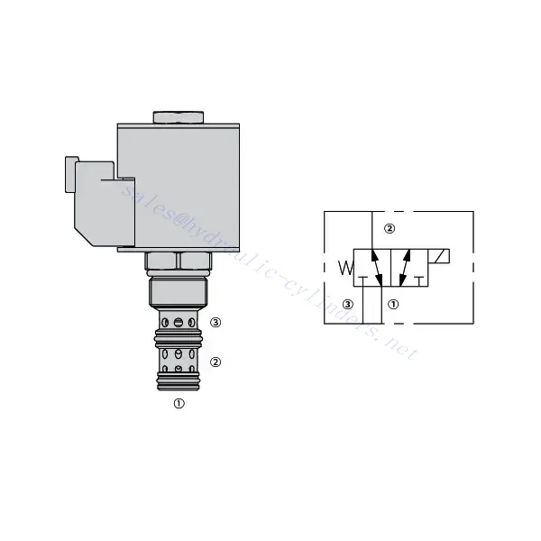
Katup Pengarah Solenoid 30SD10-34
Sebagai salah satu produsen, pemasok, dan eksportir silinder hidrolik, Kami menawarkan silinder hidrolik dan banyak produk lainnya.
Silakan hubungi kami untuk informasi lebih lanjut.
Surat:sales@hydraulic-cylinders.net
Produsen pemasok eksportir silinder hidrolik.
Katup Pengarah Solenoid 30SD10-34
Katup pengarah solenoid 30SD10-34 adalah komponen industri mutakhir yang dirancang untuk memberikan kontrol fluida yang presisi dan andal dalam berbagai aplikasi. Dengan fitur-fitur canggihnya, konstruksi yang tahan lama, dan desain yang ramah pengguna, katup pengarah solenoid ini menawarkan peningkatan kinerja dan efisiensi.
Katup solenoid pengarah 30SD10-34 adalah komponen yang andal dan serbaguna yang menawarkan kontrol fluida yang presisi dalam aplikasi industri. Konstruksinya yang kokoh, kontrol yang presisi, dan kinerja yang andal menjadikannya pilihan ideal untuk meningkatkan efisiensi dan produktivitas sistem kontrol fluida Anda. Dengan mengikuti metode penggunaan dan panduan perawatan yang direkomendasikan, Anda dapat memastikan kinerja optimal dan umur panjang katup solenoid pengarah 30SD10-34 dalam operasi industri Anda.
Karakteristik Katup Pengarah Solenoid 30SD10-34:
- Konstruksi Kokoh: Katup solenoid pengarah 30SD10-34 dibuat dengan material berkualitas tinggi dan pengerjaan yang teliti, memastikan daya tahan dan umur pakai yang panjang. Konstruksinya yang kokoh memungkinkan katup ini untuk tahan terhadap lingkungan industri yang menuntut, memberikan kinerja yang andal bahkan dalam kondisi yang sulit.
- Fungsionalitas Serbaguna: Katup pengarah solenoid ini menawarkan fungsionalitas serbaguna, sehingga cocok untuk berbagai aplikasi. Katup ini secara efektif mengontrol arah aliran fluida, memungkinkan pengoperasian yang presisi dan efisien dalam berbagai sistem industri.
- Kontrol Presisi: Dengan presisi yang luar biasa, katup arah solenoida 30SD10-34 memungkinkan kontrol akurat atas aliran fluida. Katup ini memungkinkan pengaturan dan penyesuaian arah dan tekanan fluida secara tepat, memastikan kinerja dan efisiensi optimal dalam proses industri.
- Performa Andal: Katup arah solenoid ini memberikan performa yang andal, meminimalkan risiko kegagalan atau gangguan sistem. Katup ini beroperasi dengan dapat diandalkan, berkontribusi pada peningkatan produktivitas dan pengurangan waktu henti dalam operasi industri.
Parameter Katup Pengarah Solenoid 30SD10-34:
| Tekanan terukur | 207 bar (3000 psi) | |
| Tekanan bukti | 350 bar (5075 psi) | |
| Aliran puncak | 22,7 L/menit (6 gpm) | |
| Cairan | Berbasis mineral atau sintetis dengan sifat pelumas | |
| Kisaran suhu ℃ | -54 hingga 107 ℃ (Segel poliuretan) | |
| -40 hingga 100 ℃ (segel Buna N) | ||
| -26 hingga 204 ℃ (Segel fluorokarbon) | ||
| Kisaran viskositas | 7,4 hingga 420 mm2/S | |
| Tingkat kontaminasi | Tingkat polusi minimum adalah level ISO4406 20/18/14, dan level 17/15/13 direkomendasikan untuk memperpanjang masa pakai | |
| Kebocoran Internal | ≤ 115 mL/min@207bar | |
| Rongga | VC10-3 | |
| Peringkat Tugas Kumparan | Kontinu dari 85% hingga 115% tegangan nominal | |
| Waktu respon | Indikasi pertama perubahan status dengan tegangan 100% yang diberikan pada rating aliran nominal 80%: Aktif: 60 msec. ; Tidak aktif: 10 msec. | |
| Penarikan Arus Kumparan Awal pada 20℃ | kumparan elektronik | 1,7A pada 12VDC; 0,85A pada 24VDC |
| kumparan D | 1,67A pada 12VDC; 0,83A pada 24VDC | |
| Tegangan tarik minimum | 85% nominal pada 207 bar | |
Keunggulan Katup Pengarah Solenoid 30SD10-34:
• Kumparan dengan rating tugas kontinu
• Konstruksi rangka basah yang efisien
• Kartrid dapat dipertukarkan tegangannya
• E-Coil tahan air opsional dengan peringkat hingga IP69K
• Semua port dapat diberi tekanan penuh
• Rongga umum industri
• Bagian yang diperkeras untuk umur panjang dan kebocoran rendah
Metode Penggunaan Katup Pengarah Solenoid 30SD10-34:
- Integrasi ke dalam Sistem: Integrasikan katup arah solenoid 30SD10-34 ke dalam sistem kontrol fluida sesuai dengan panduan dan spesifikasi pabrikan. Pastikan penyelarasan dan koneksi yang tepat antara katup dan komponen sistem lainnya untuk mencapai kinerja optimal.
- Sambungan Listrik: Pasang sambungan listrik yang aman untuk katup arah solenoid. Lihat diagram pengkabelan yang disediakan dan pastikan polaritas yang benar untuk mencegah kerusakan listrik. Ikuti pedoman keselamatan saat bekerja dengan sambungan listrik.
- Kontrol Arah Aliran Fluida: Gunakan katup solenoid arah untuk mengontrol arah aliran fluida. Katup ini biasanya dilengkapi dengan tuas atau aktuator untuk pengaturan manual. Sebagai alternatif, katup ini dapat diintegrasikan ke dalam sistem kontrol otomatis untuk pengoperasian jarak jauh.
- Pengaturan Tekanan: Gunakan katup arah solenoid untuk mengatur tekanan fluida di dalam sistem. Dengan menyesuaikan pengaturan katup, Anda dapat mencapai tingkat tekanan yang diinginkan untuk kinerja dan efisiensi optimal.
Bagaimana Cara Memasang Katup Hidrolik Siklus Otomatis?
Pemasangan katup hidrolik siklus otomatis memerlukan perhatian cermat untuk memastikan pemasangan dan fungsionalitas yang tepat. Ikuti langkah-langkah berikut untuk memasang katup hidrolik siklus otomatis secara efektif:
- Kumpulkan Alat dan Bahan yang Diperlukan: Sebelum memulai, pastikan Anda memiliki semua alat dan bahan yang dibutuhkan, termasuk selang hidrolik, fitting, adaptor, pita Teflon, kunci pas, dan reservoir cairan hidrolik.
- Identifikasi Port Katup: Periksa katup hidrolik siklus otomatis untuk mengidentifikasi berbagai port. Biasanya, akan ada port masuk, port keluar, dan mungkin port tambahan untuk pelepas tekanan atau fungsi bantu.
- Tentukan Arah Aliran Fluida Hidraulik: Tentukan arah aliran fluida hidrolik yang diinginkan melalui katup. Informasi ini sangat penting untuk menghubungkan port masuk dan keluar dengan benar.
- Pasang Fitting dan Adaptor: Pasang fitting dan adaptor yang sesuai pada port katup. Pastikan semuanya dikencangkan dengan aman, tetapi berhati-hatilah agar tidak terlalu kencang dan merusak ulir.
- Gunakan Pita Teflon: Lilitkan pita Teflon di sekeliling ulir fitting dan adaptor. Ini membantu menciptakan segel yang rapat dan mencegah kebocoran.
- Menghubungkan Selang Hidrolik: Pasang selang hidrolik ke fitting dan adaptor pada port katup. Pastikan selang tersebut sesuai dengan peringkat tekanan sistem hidrolik dan memiliki panjang yang tepat.
- Pastikan Sambungan Selang Aman: Gunakan klem selang atau metode lain yang sesuai untuk mengamankan selang hidrolik ke fitting. Ini mencegah selang terlepas selama pengoperasian.
- Rute Selang Hidrolik: Arahkan selang hidrolik dengan hati-hati untuk menghubungkan katup hidrolik siklus otomatis ke reservoir cairan hidrolik dan komponen hidrolik lainnya, seperti silinder atau motor. Hindari tikungan tajam atau lekukan pada selang yang dapat membatasi aliran cairan.
- Periksa Kebocoran: Setelah semua sambungan terpasang, periksa kebocoran. Mulailah dengan perlahan memberi tekanan pada sistem dan periksa setiap titik sambungan. Jika Anda melihat kebocoran, kencangkan sambungan atau ganti komponen yang rusak jika perlu.
- Isi Tangki Cairan Hidrolik: Isi reservoir cairan hidrolik dengan jenis dan jumlah cairan hidrolik yang direkomendasikan. Lihat panduan pabrikan untuk spesifikasi cairan yang sesuai.
- Keluarkan Udara dari Sistem: B. Buang udara yang terjebak dalam sistem hidrolik untuk memastikan pengoperasian yang benar. Ikuti petunjuk pabrikan untuk prosedur pembuangan udara, yang biasanya melibatkan pengoperasian sistem dan membuka katup pembuangan udara.
- Uji Sistem: Setelah pemasangan pipa selesai, uji katup hidrolik siklus otomatis dan kinerja sistem secara keseluruhan. Pastikan katup berfungsi sebagaimana mestinya dan aliran fluida lancar dan konsisten.
Kemampuan & Kapasitas Pabrik:
(1) Perakitan
Kami memiliki platform perakitan penelitian dan pengembangan independen kelas satu. Bengkel produksi silinder hidrolik memiliki empat jalur perakitan silinder pengangkat semi-otomatis dan satu jalur perakitan silinder kemiringan otomatis, dengan kapasitas produksi tahunan yang dirancang sebesar 1 juta keping. Bengkel silinder khusus dilengkapi dengan berbagai spesifikasi sistem perakitan pembersihan semi-otomatis dengan kapasitas produksi tahunan yang dirancang sebesar 200.000 dan dilengkapi dengan peralatan permesinan CNC yang terkenal, pusat permesinan, peralatan khusus pemrosesan silinder presisi tinggi, mesin las robot, mesin pembersih otomatis, mesin perakitan silinder otomatis, dan jalur produksi pengecatan otomatis. Peralatan penting yang ada lebih dari 300 set (set). Alokasi optimal dan penggunaan sumber daya peralatan yang efisien memastikan persyaratan akurasi produk dan memenuhi kebutuhan produk berkualitas tinggi.


(2) Pemesinan
Bengkel permesinan dilengkapi dengan pusat pembubutan rel miring yang disesuaikan, pusat permesinan, mesin pengasah berkecepatan tinggi, robot pengelasan, dan peralatan terkait lainnya, yang dapat menangani pemrosesan tabung silinder dengan diameter bagian dalam maksimum 400mm dan panjang maksimum 6 meter.

(3) Pengelasan

(4) Pengecatan & pelapisan
Dengan jalur pelapisan cat berbasis air otomatis silinder kecil dan menengah, untuk mencapai bongkar muat robot otomatis dan penyemprotan otomatis, kapasitas desain 4000 buah per shift;
Kami juga memiliki lini produksi cat semi-otomatis untuk silinder besar yang ditenagai oleh rantai daya, dengan kapasitas desain 60 kasus per shift.


(5) Pengujian
Kami memiliki fasilitas inspeksi kelas satu dan test bed untuk memastikan bahwa kinerja silinder memenuhi persyaratan.

Kami adalah salah satu produsen silinder hidrolik terbaik. Kami dapat menawarkan silinder hidrolik yang lengkap. Kami juga menyediakan produk yang sesuai. gearbox pertanian. Kami telah mengekspor produk kami ke klien di seluruh dunia dan mendapatkan reputasi yang baik karena kualitas produk dan layanan purna jual kami yang unggul. Kami menyambut pelanggan di dalam dan luar negeri untuk menghubungi kami untuk menegosiasikan bisnis, bertukar informasi, dan bekerja sama dengan kami!
Aplikasi Silinder Hidraulik:
