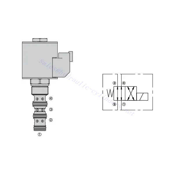
30SD10-40 Solenoid Directional Valve
30SD10-40 Solenoid Directional Valve
The 30SD10-40 solenoid directional valve is a high-performance industrial component designed to deliver precise and reliable fluid control in a variety of applications. With its advanced features, durable construction, and user-friendly design, this solenoid directional valve offers enhanced efficiency and operational reliability.
The 30SD10-40 solenoid directional valve is a reliable and versatile component that offers precise fluid control in industrial applications. Its robust construction, precision control, and reliable performance enhance efficiency and productivity in fluid control systems. By following the recommended usage methods and maintenance guidelines, you can ensure optimal performance and longevity of the 30SD10-40 solenoid directional valve in your industrial operations.
30SD10-40 Solenoid Directional Valve Characteristics:
- Robust Construction: The 30SD10-40 solenoid directional valve is built with exceptional craftsmanship and high-quality materials, ensuring durability and longevity. Its sturdy construction allows it to withstand demanding industrial environments, providing reliable performance even in harsh conditions.
- Versatile Functionality: This solenoid directional valve offers versatile functionality, making it suitable for a wide range of applications. It effectively controls the direction of fluid flow, enabling precise and efficient operation in various industrial systems.
- Precision Control: The 30SD10-40 solenoid directional valve provides exceptional precision in fluid control. It allows for accurate regulation and adjustment of fluid direction and pressure, ensuring optimal performance and efficiency in industrial processes.
- Reliable Performance: This solenoid directional valve delivers reliable performance, minimizing the risk of system failures or interruptions. It operates with dependability, contributing to increased productivity and reduced downtime in industrial operations.
30SD10-40 Solenoid Directional Valve Parameter:
| Tekanan terukur | 207 bar (3000 psi) | |
| Aliran puncak | 23 L/menit (6 gpm) | |
| Cairan | Berbasis mineral atau sintetis dengan sifat pelumas | |
| Kisaran suhu ℃ | -54 hingga 107 ℃ (Segel poliuretan) | |
| -40 hingga 100 ℃ (segel Buna N) | ||
| -26 hingga 204 ℃ (Segel fluorokarbon) | ||
| Kisaran viskositas | 7,4 hingga 420 mm2/S | |
| Tingkat kontaminasi | Tingkat polusi minimum adalah level ISO4406 20/18/14, dan level 17/15/13 direkomendasikan untuk memperpanjang masa pakai | |
| Kebocoran Internal | ≤ 82 mL/menit@207bar | |
| Rongga | VC10-4 | |
| Peringkat Tugas Kumparan | Kontinu dari 85% hingga 115% tegangan nominal | |
| Penarikan Arus Kumparan Awal pada 20℃ | kumparan elektronik | 1,7A pada 12VDC; 0,85A pada 24VDC |
| kumparan D | 1,67A pada 12VDC; 0,83A pada 24VDC | |
| Tegangan tarik minimum | 85% nominal pada 207 bar | |
30SD10-40 Solenoid Directional Valve Advantages:
• Kumparan dengan rating tugas kontinu
• Kartrid dapat dipertukarkan tegangannya
• E-Coil tahan air opsional dengan peringkat hingga IP69K
• Konstruksi rangka basah yang efisien
• Rongga umum industri
• Bagian yang diperkeras untuk umur panjang
Usage Method Of 30SD10-40 Solenoid Directional Valve :
- Integration into the System: Integrate the 30SD10-40 Solenoid Directional Valve into the fluid control system following the manufacturer’s guidelines and specifications. Ensure proper alignment and connection between the valve and other system components to achieve optimal performance.
- Electrical Connection: Establish a secure electrical connection for the solenoid directional valve. Follow the provided wiring diagram and ensure correct polarity to prevent electrical malfunctions. Adhere to safety guidelines when working with electrical connections.
- Kontrol Arah Aliran Fluida: Gunakan katup solenoid arah untuk mengontrol arah aliran fluida. Katup ini biasanya dilengkapi dengan tuas atau aktuator untuk pengaturan manual. Sebagai alternatif, katup ini dapat diintegrasikan ke dalam sistem kontrol otomatis untuk pengoperasian jarak jauh.
- Pressure Adjustment: Use the solenoid directional valve to regulate fluid pressure within the system. Adjust the valve’s settings to achieve the desired pressure levels for optimal performance and efficiency.
How To Read Hydraulic Valve Schematics?
Reading hydraulic valve schematics requires a basic understanding of hydraulic symbols and their meanings. Here are the steps to help you read hydraulic valve schematics:
- Familiarize Yourself With Hydraulic Symbols: Hydraulic schematics use graphical symbols to represent various components and functions. Common symbols include squares for valves, lines for pipes or hoses, arrows for flow direction, and circles for pressure or flow control devices. Make sure you understand the meaning of these symbols before proceeding.
- Identify The Valve Types: Look for the valve symbols in the schematic. Valves can be represented by squares with different shapes and orientations. For example, a square with a diagonal line represents a check valve, while a square with an arrow inside denotes a directional control valve.
- Determine The Valve Function: Each valve symbol indicates its specific function. Directional control valves determine the flow direction of hydraulic fluid, while pressure control valves regulate pressure levels. Flow control valves manage the rate of fluid flow, and check valves allow flow in one direction only.
- Observe The Valve Connections: Pay attention to the lines or arrows entering and exiting the valve symbol. These lines represent the hydraulic fluid flow paths. Arrows indicate the flow direction, and lines connecting valves and other components indicate the connections.
- Analyze The Valve Ositions: Some hydraulic valve schematics include symbols to illustrate the valve positions. These symbols typically depict the valve spool or lever in different positions, such as open, closed, or partially open. Understanding the valve positions helps you determine the flow paths and the state of the hydraulic system.
- Consider Additional Symbols And Annotations: Hydraulic schematics may include additional symbols and annotations to indicate pressure gauges, flow meters, filters, accumulators, or other components. Familiarize yourself with these symbols and their meanings to gain a comprehensive understanding of the system.
- Follow The Flow Paths: Trace the flow paths from the hydraulic power source through the various valves and components to the actuator or desired output. Understand how the valves interact with one another and how they control fluid flow, pressure, and direction to achieve the desired system operation.
- Refer To The Legend Or Key: The schematic should have a legend or key that explains the meaning of each symbol used in the diagram. If you encounter unfamiliar symbols or have doubts about their meaning, refer to the legend for clarification.
- Seek Additional Resources If Needed: If you need a more in-depth understanding of hydraulic valve schematics, consider referring to hydraulic textbooks, online resources, or consulting with hydraulic experts who can provide guidance and explanations tailored to your specific needs.
Kemampuan & Kapasitas Pabrik:
(1) Perakitan
Kami memiliki platform perakitan penelitian dan pengembangan independen kelas satu. Bengkel produksi silinder hidrolik memiliki empat jalur perakitan silinder pengangkat semi-otomatis dan satu jalur perakitan silinder kemiringan otomatis, dengan kapasitas produksi tahunan yang dirancang sebesar 1 juta keping. Bengkel silinder khusus dilengkapi dengan berbagai spesifikasi sistem perakitan pembersihan semi-otomatis dengan kapasitas produksi tahunan yang dirancang sebesar 200.000 dan dilengkapi dengan peralatan permesinan CNC yang terkenal, pusat permesinan, peralatan khusus pemrosesan silinder presisi tinggi, mesin las robot, mesin pembersih otomatis, mesin perakitan silinder otomatis, dan jalur produksi pengecatan otomatis. Peralatan penting yang ada lebih dari 300 set (set). Alokasi optimal dan penggunaan sumber daya peralatan yang efisien memastikan persyaratan akurasi produk dan memenuhi kebutuhan produk berkualitas tinggi.


(2) Pemesinan
Bengkel permesinan dilengkapi dengan pusat pembubutan rel miring yang disesuaikan, pusat permesinan, mesin pengasah berkecepatan tinggi, robot pengelasan, dan peralatan terkait lainnya, yang dapat menangani pemrosesan tabung silinder dengan diameter bagian dalam maksimum 400mm dan panjang maksimum 6 meter.

(3) Pengelasan

(4) Pengecatan & pelapisan
Dengan jalur pelapisan cat berbasis air otomatis silinder kecil dan menengah, untuk mencapai bongkar muat robot otomatis dan penyemprotan otomatis, kapasitas desain 4000 buah per shift;
Kami juga memiliki lini produksi cat semi-otomatis untuk silinder besar yang ditenagai oleh rantai daya, dengan kapasitas desain 60 kasus per shift.


(5) Pengujian
Kami memiliki fasilitas inspeksi kelas satu dan test bed untuk memastikan bahwa kinerja silinder memenuhi persyaratan.

Kami adalah salah satu produsen silinder hidrolik terbaik. Kami dapat menawarkan silinder hidrolik yang lengkap. Kami juga menyediakan produk yang sesuai. gearbox pertanian. Kami telah mengekspor produk kami ke klien di seluruh dunia dan mendapatkan reputasi yang baik karena kualitas produk dan layanan purna jual kami yang unggul. Kami menyambut pelanggan di dalam dan luar negeri untuk menghubungi kami untuk menegosiasikan bisnis, bertukar informasi, dan bekerja sama dengan kami!


