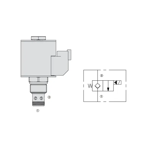
35SD10-20 Solenoid Directional Valve
Sebagai salah satu produsen, pemasok, dan eksportir silinder hidrolik, Kami menawarkan silinder hidrolik dan banyak produk lainnya.
Silakan hubungi kami untuk informasi lebih lanjut.
Surat:sales@hydraulic-cylinders.net
Produsen pemasok eksportir silinder hidrolik.
35SD10-20 Solenoid Directional Valve
The 35SD10-20 Solenoid Directional Valve is a powerful and versatile component designed to optimize fluid control in a wide range of industrial applications. With its advanced features, precise operation, and reliable performance, this solenoid valve is a valuable tool for enhancing fluid control efficiency and productivity. Whether in manufacturing, automation, or process control, the 35SD10-20 Solenoid Directional Valve delivers exceptional functionality and versatility, making it an essential component for modern industries.
The 30SD08-47D Solenoid Directional Valve is a reliable and versatile component that optimizes fluid control in various industrial applications. With its robust construction, precise fluid control, versatility, and space-efficient design, this solenoid valve offers exceptional performance, ensuring efficient and reliable operations. By incorporating the 30SD08-47D Solenoid Directional Valve into fluid control systems, industries can achieve enhanced productivity, accuracy, and system performance. Invest in this advanced solenoid valve to optimize your industrial processes, streamline operations, and achieve success in your industry.
35SD10-20 Solenoid Directional Valve Characteristics:
- Robust Construction: The 35SD10-20 Solenoid Directional Valve is built with a robust and durable design, ensuring long-lasting performance even in demanding environments. Its sturdy construction allows it to withstand high pressures, temperature fluctuations, and harsh conditions, providing consistent and reliable operation.
- Precise Fluid Control: This solenoid valve offers precise control over fluid flow, enabling accurate and efficient regulation of liquids or gases. With its responsive solenoid mechanism, the valve allows for fast and reliable switching between different flow paths, ensuring precise control and minimizing flow disruptions.
- Versatile Functionality: The 35SD10-20 Solenoid Directional Valve is designed to accommodate various applications in different industries. It can be used for direction control, on/off switching, and pressure regulation, providing flexibility and adaptability in fluid control systems.
- Efficient Energy Consumption: This solenoid valve is designed with energy efficiency in mind. It minimizes power consumption during operation, resulting in cost savings and environmental benefits. The valve’s efficient energy usage makes it a sustainable choice for businesses looking to optimize their resource utilization.
35SD10-20 Solenoid Directional Valve Parameter:
| Tekanan terukur | 241 bar (3500 psi) | |
| Aliran puncak | 56.8 L/min (15 gpm) ; See performance chart | |
| Cairan | Berbasis mineral atau sintetis dengan sifat pelumas | |
| Kisaran suhu fluida ℃ | -54 hingga 107 ℃ (Segel poliuretan) | |
| -40 hingga 100 ℃ (segel Buna N) | ||
| -26 hingga 204 ℃ (Segel fluorokarbon) | ||
| Kisaran viskositas | 7,4 hingga 420 mm2/S | |
| Tingkat kontaminasi | Tingkat polusi minimum adalah level ISO4406 18/16/13, dan level 15/13/11 direkomendasikan untuk memperpanjang masa pakai | |
| Kebocoran Internal | ≤ 0.15 mL/min (3 drops /min) @241 bar | |
| Rongga | VC10-2 | |
| Peringkat Tugas Kumparan | Kontinu dari 85% hingga 115% tegangan nominal | |
| Penarikan Arus Kumparan Awal pada 20℃ | kumparan elektronik | 1,7A pada 12VDC; 0,85A pada 24VDC |
| kumparan D | 1,67A pada 12VDC; 0,83A pada 24VDC | |
| Tegangan tarik minimum | 85% of nominal at 241 bar | |
35SD10-20 Solenoid Directional Valve Advantages:
• Kumparan dengan rating tugas kontinu
• Konstruksi rangka basah yang efisien
• Kartrid dapat dipertukarkan tegangannya
• E-Coil tahan air opsional dengan peringkat hingga IP69K
• Rongga umum industri
• Bagian yang diperkeras untuk umur panjang dan kebocoran rendah
Usage Method Of 35SD10-20 Solenoid Directional Valve:
Instalasi:
- Follow the manufacturer’s instructions for proper installation of the 35SD10-20 Solenoid Directional Valve.
- Ensure correct alignment and connection to the fluid control system, using appropriate fittings and seals for leak-free operation.
Sambungan Listrik:
- Connect the solenoid valve to the power supply, following the specified voltage and electrical requirements.
- Ensure proper wiring and insulation to ensure safe and reliable electrical operation.
Arah Aliran Fluida:
- Determine the desired fluid flow direction based on your application requirements.
- The 35SD10-20 Solenoid Directional Valve provides various ports and positions for inlet, outlet, and exhaust. Consult the product documentation for correct port connections.
Control Signal:
- Connect the control signal, whether electrical or pneumatic, to the solenoid valve to activate its switching mechanism.
- Ensure that the control signal is compatible with the valve’s specifications and operating parameters.
Bagaimana Cara Memasang Katup Kontrol Aliran Hidrolik?
Untuk memasang katup kontrol aliran hidrolik, ikuti langkah-langkah berikut:
- Identifikasi Jenis Katup: Tentukan jenis katup kontrol aliran yang Anda gunakan. Jenis yang umum digunakan antara lain katup jarum, katup kontrol aliran yang dapat disesuaikan, atau katup kontrol aliran dengan kompensasi tekanan. Pastikan katup tersebut sesuai dengan aplikasi Anda dan kompatibel dengan sistem hidrolik Anda.
- Kumpulkan Alat dan Bahan yang Diperlukan: Kumpulkan peralatan dan bahan yang diperlukan, termasuk perlengkapan hidrolik, adaptor, selang, dan kunci pas yang sesuai.
- Siapkan Sistem Hidrolik: Matikan sistem hidrolik dan kurangi tekanan dalam sistem dengan mengaktifkan katup pelepas atau menarik silinder hidrolik. Langkah ini penting untuk keselamatan.
- Identifikasi Arah Aliran: Identifikasi arah aliran dalam sistem hidrolik Anda. Biasanya, arah aliran ditunjukkan oleh tanda panah pada komponen hidrolik. Pastikan Anda memahami arah aliran yang benar sebelum melanjutkan.
- Temukan Titik Instalasi: Tentukan lokasi optimal untuk memasang katup kontrol aliran pada sistem hidrolik Anda. Pertimbangkan faktor-faktor seperti aksesibilitas, kedekatan dengan aktuator atau komponen hidrolik, dan kemudahan penyesuaian.
- Pasang Katup: Pasang katup pengatur aliran dengan aman di lokasi yang dipilih menggunakan braket atau klem yang sesuai. Pastikan katup diposisikan dengan benar, sejajarkan lubang masuk dan keluar dengan arah aliran.
- Hubungkan Port Masuk dan Keluar: Pasang selang atau pipa hidrolik ke port masuk dan keluar katup kontrol aliran. Gunakan fitting dan adaptor hidrolik yang sesuai untuk memastikan sambungan bebas kebocoran. Kencangkan sambungan menggunakan kunci inggris untuk memastikan sambungan terpasang dengan benar, tetapi hindari mengencangkannya terlalu kencang.
- Sesuaikan Kontrol Aliran: Tergantung pada jenis katup pengontrol aliran, katup tersebut mungkin memiliki fitur yang dapat disesuaikan seperti katup jarum atau kenop pengontrol aliran. Sesuaikan katup sesuai dengan laju atau kecepatan aliran yang Anda inginkan. Lihat petunjuk produsen untuk prosedur penyesuaian spesifik.
- Uji Sistem: Setelah katup kontrol aliran dipasang dan disetel, kembalikan tekanan sistem hidrolik secara perlahan. Uji sistem untuk memastikan katup kontrol aliran berfungsi dengan benar. Pantau laju aliran atau kecepatan aktuator hidrolik untuk memastikannya berada dalam rentang yang diinginkan.
- Penyetelan halus dan pantau: Sesuaikan katup kontrol aliran untuk mencapai laju atau kecepatan aliran yang diinginkan. Pantau sistem hidrolik secara berkala untuk mendeteksi kebocoran, ketidakkonsistenan tekanan, atau perilaku yang tidak biasa.
Kemampuan & Kapasitas Pabrik:
(1) Perakitan
Kami memiliki platform perakitan penelitian dan pengembangan independen kelas satu. Bengkel produksi silinder hidrolik memiliki empat jalur perakitan silinder pengangkat semi-otomatis dan satu jalur perakitan silinder kemiringan otomatis, dengan kapasitas produksi tahunan yang dirancang sebesar 1 juta keping. Bengkel silinder khusus dilengkapi dengan berbagai spesifikasi sistem perakitan pembersihan semi-otomatis dengan kapasitas produksi tahunan yang dirancang sebesar 200.000 dan dilengkapi dengan peralatan permesinan CNC yang terkenal, pusat permesinan, peralatan khusus pemrosesan silinder presisi tinggi, mesin las robot, mesin pembersih otomatis, mesin perakitan silinder otomatis, dan jalur produksi pengecatan otomatis. Peralatan penting yang ada lebih dari 300 set (set). Alokasi optimal dan penggunaan sumber daya peralatan yang efisien memastikan persyaratan akurasi produk dan memenuhi kebutuhan produk berkualitas tinggi.


(2) Pemesinan
Bengkel permesinan dilengkapi dengan pusat pembubutan rel miring yang disesuaikan, pusat permesinan, mesin pengasah berkecepatan tinggi, robot pengelasan, dan peralatan terkait lainnya, yang dapat menangani pemrosesan tabung silinder dengan diameter bagian dalam maksimum 400mm dan panjang maksimum 6 meter.

(3) Pengelasan

(4) Pengecatan & pelapisan
Dengan jalur pelapisan cat berbasis air otomatis silinder kecil dan menengah, untuk mencapai bongkar muat robot otomatis dan penyemprotan otomatis, kapasitas desain 4000 buah per shift;
Kami juga memiliki lini produksi cat semi-otomatis untuk silinder besar yang ditenagai oleh rantai daya, dengan kapasitas desain 60 kasus per shift.


(5) Pengujian
Kami memiliki fasilitas inspeksi kelas satu dan test bed untuk memastikan bahwa kinerja silinder memenuhi persyaratan.

Kami adalah salah satu produsen silinder hidrolik terbaik. Kami dapat menawarkan silinder hidrolik yang lengkap. Kami juga menyediakan produk yang sesuai. gearbox pertanian. Kami telah mengekspor produk kami ke klien di seluruh dunia dan mendapatkan reputasi yang baik karena kualitas produk dan layanan purna jual kami yang unggul. Kami menyambut pelanggan di dalam dan luar negeri untuk menghubungi kami untuk menegosiasikan bisnis, bertukar informasi, dan bekerja sama dengan kami!
Aplikasi Silinder Hidraulik:
