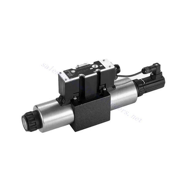
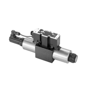
4WRE(E) Series Proportional Directional Hydraulic Valve
Sebagai salah satu produsen, pemasok, dan eksportir silinder hidrolik, Kami menawarkan silinder hidrolik dan banyak produk lainnya.
Silakan hubungi kami untuk informasi lebih lanjut.
Surat:sales@hydraulic-cylinders.net
Produsen pemasok eksportir silinder hidrolik.
4WRE(E) Series Proportional Directional Hydraulic Valve
The 4WRE(E) series proportional directional hydraulic valve is a cutting-edge hydraulic component designed to deliver precise control and exceptional performance in hydraulic systems. This valve utilizes advanced proportional control technology to ensure accurate flow regulation and seamless directional changes.
The 4WRE(E) series proportional directional hydraulic valve empowers hydraulic systems with precise flow control, versatile directional changes, and energy efficiency. Its proportional control technology enables accurate and responsive flow adjustment, while the high flow capacity ensures reliable performance even in demanding applications. By following the recommended usage methods and maintenance guidelines, you can maximize the benefits and longevity of the 4WRE(E) series valve, elevating your hydraulic system to new levels of precision and performance. Upgrade your hydraulic setup today and experience the power of the 4WRE(E) series proportional directional hydraulic valve.
4WRE(E) Series Proportional Directional Hydraulic Valve Key Characteristics:
- Proportional Control Technology:
- The 4WRE(E) series valve features advanced proportional control technology, allowing for precise and proportional flow adjustment according to control signals.
- This feature enables accurate and responsive control, resulting in improved system performance and efficiency.
- Versatile Directional Control:
- With its proportional directional control capability, this valve offers versatile control over hydraulic fluid direction.
- It allows for seamless activation and deactivation of hydraulic components such as cylinders, motors, and actuators in different directions, enhancing system flexibility and productivity.
- Kapasitas Aliran Tinggi:
- The 4WRE(E) series valve is designed to handle high flow rates, making it suitable for applications requiring substantial hydraulic power.
- Its robust construction ensures reliable performance even under demanding conditions, providing consistent and efficient flow control.
- Efisiensi Energi:
- By employing advanced flow control mechanisms, this valve minimizes pressure drops and optimizes energy usage.
- It helps reduce energy consumption, resulting in cost savings and environmental benefits.
4WRE(E) Series Proportional Directional Hydraulic Valve Parameter:
| Hidrolik | ||||
| Posisi pemasangan | Opsional, sebaiknya horizontal. | |||
| Ukuran | 6 | 10 | ||
| Berat | 4WRE…L2X | kg | 2.2 | 6.3 |
| 4WREE…L2X | 2.4 | 6.5 | ||
| Nominal flow qnom at Δp = 10 bar | L/menit | 8 16 32 | 25 50 75 | |
| Histeresis | % | ≤0.1 | ||
| Reversal span | % | ≤0.05 | ||
| Pengulangan | % | ≤0.05 | ||
| Tekanan operasi maks. | Port s ABP | batang | 315 | |
| Pelabuhan T | batang | 210 | ||
| Cairan | Oli mineral cocok untuk seal NBR dan FKM | |||
| Ester fosfat untuk segel FKM | ||||
| Ambient air temperature range | 4WRA…L2X | ℃ | -20℃ to 70℃ (-4°F to 158°F) | |
| 4WRAE…L2X | ℃ | -20℃ to 50℃ (-4°F to 122°F) | ||
| Kisaran viskositas | mm²/detik | 20 hingga 380 (lebih disukai 30 hingga 46) | ||
| Tingkat kontaminasi | NAS1638 kelas 9 atau ISO 4406 kelas 20/18/15 | |||
| Data listrik | ||||
| 1) solenoida | ||||
| Ukuran | 6 | 10 | ||
| Jenis tegangan | DC | |||
| Sinyal nilai perintah | ±10V atau 4~20mA | |||
| Max.current per solenoid | A | 2.5 | ||
| Resistansi kumparan | Nilai dingin | Ω | 2.7 | 3.7 |
| Nilai hangat maksimum | 4.05 | 5.55 | ||
| Tugas | % | ED 100% | ||
| Suhu kumparan | ℃ | 150 | ||
| Perlindungan katup sesuai dengan EN 60529 | IP 65 | |||
| 2) Control electronics | ||||
| Penguat | 4WRE…L2X | VT-VSPA2-L2X | ||
| 4WREE…L2X | integrated(OBE) | |||
| Tegangan operasi | Tegangan nominal | VDC | 24 | |
| Nilai batas bawah | V | 19.4 | ||
| nilai batas atas | V | 35 | ||
| Konsumsi arus penguat | Imax | A | < 2 | |
| Imax | A | 3 | ||
4WRE(E) Series Proportional Directional Hydraulic Valve Advantages:
• Direct-acting proportional directional valve, used to control the flow and direction of liquid flow
• Instalasi tipe panel
• The proportional solenoid actuates the valve core through the threaded connection, and the coil can be removed separately
• Spool position feedback
• Optional with built-in amplifier, 4WRAE…L2X type input can be A1 or F1
• Mendukung pasokan penguat eksternal
Usage Method Of 4WRE(E) Series Proportional Directional Hydraulic Valve:
- Evaluasi Sistem:
- Evaluate your hydraulic system and identify the specific flow and directional control requirements.
- Determine if the 4WRE(E) series valve is suitable based on its flow capacity, pressure rating, and compatibility with your system.
- Pemilihan Katup:
- Select the appropriate variant of the 4WRE(E) series valve based on your system parameters, flow requirements, and directional control needs.
- Consider factors such as maximum flow rate, pressure rating, response time, and operational conditions.
- Instalasi:
- Follow the manufacturer’s installation instructions carefully, ensuring proper alignment and secure mounting of the valve.
- Make leak-free connections and ensure correct flow direction alignment to guarantee optimal performance.
- Control Signal Connection:
- Hubungkan kabel sinyal kontrol katup ke perangkat kontrol yang sesuai, seperti penguat proporsional atau unit kontrol elektronik.
- Ensure proper wiring and compatibility between the valve and the control device for accurate and responsive control.
How To Adjust Valves With Hydraulic Lifters?
Adjusting valve lash on hydraulic lifters is a crucial maintenance task to ensure proper engine performance and prevent issues such as noisy valves or reduced power. Here’s a step-by-step guide on how to adjust valve lash on hydraulic lifters:
- Persiapan:
- Ensure the engine is off and cool before starting the adjustment process.
- Familiarize yourself with the engine’s firing order and the specific valve lash specifications provided by the manufacturer for your engine model.
- Identify the Correct Cylinder:
- Locate the firing position of the engine by referring to the engine’s firing order diagram.
- Identify the cylinder that corresponds to the specific valve you want to adjust.
- Posisikan Silinder:
- Rotate the engine crankshaft manually using a socket wrench or the engine’s built-in turning mechanism.
- Position the cylinder you want to adjust at the top dead center (TDC) on the compression stroke. You can do this by aligning the timing marks on the crankshaft pulley or using a piston stop tool.
- Loosen the Rocker Arm:
- Locate the rocker arm on the specific valve you want to adjust.
- Loosen the rocker arm nut or adjuster screw using an appropriate wrench or socket.
- Adjust the Valve Lash:
- With the rocker arm loose, you can now adjust the valve lash. The valve lash is the clearance between the rocker arm and the valve stem.
- Use a feeler gauge to measure the existing valve lash. Insert the appropriate thickness gauge between the rocker arm and the valve stem.
- If the clearance is too tight, meaning the feeler gauge does not fit or has excessive resistance, you need to increase the valve lash. If the clearance is too loose, meaning the feeler gauge slides in too easily, you need to decrease the valve lash.
- To adjust the valve lash, tighten or loosen the rocker arm nut or adjuster screw accordingly. Refer to the manufacturer’s specifications for the recommended amount of adjustment to be made.
- Recheck the Valve Lash:
- After making the adjustment, recheck the valve lash using the feeler gauge to ensure it falls within the recommended specifications.
- Repeat the adjustment process if necessary until the correct valve lash is achieved.
- Repeat for Other Cylinders:
- Proceed to the next cylinder in the firing order and repeat steps 4 to 6 for each cylinder you want to adjust.
- Remember to rotate the crankshaft and position each cylinder at TDC on the compression stroke before adjusting its valve lash.
- Secure the Rocker Arm:
- Once the valve lash is properly adjusted for each cylinder, tighten the rocker arm nut or adjuster screw to the manufacturer’s recommended torque specification.
- Double-check that the valve lash remains within the specified range after tightening.
- Final Checks:
- Rotate the engine crankshaft a few times to ensure smooth rotation and check for any unusual noises or resistance.
- Start the engine and listen for any abnormal valve noises. If you hear excessive tapping or knocking, recheck the valve lash adjustment.
Kemampuan & Kapasitas Pabrik:
(1) Perakitan
Kami memiliki platform perakitan penelitian dan pengembangan independen kelas satu. Bengkel produksi silinder hidrolik memiliki empat jalur perakitan silinder pengangkat semi-otomatis dan satu jalur perakitan silinder kemiringan otomatis, dengan kapasitas produksi tahunan yang dirancang sebesar 1 juta keping. Bengkel silinder khusus dilengkapi dengan berbagai spesifikasi sistem perakitan pembersihan semi-otomatis dengan kapasitas produksi tahunan yang dirancang sebesar 200.000 dan dilengkapi dengan peralatan permesinan CNC yang terkenal, pusat permesinan, peralatan khusus pemrosesan silinder presisi tinggi, mesin las robot, mesin pembersih otomatis, mesin perakitan silinder otomatis, dan jalur produksi pengecatan otomatis. Peralatan penting yang ada lebih dari 300 set (set). Alokasi optimal dan penggunaan sumber daya peralatan yang efisien memastikan persyaratan akurasi produk dan memenuhi kebutuhan produk berkualitas tinggi.


(2) Pemesinan
Bengkel permesinan dilengkapi dengan pusat pembubutan rel miring yang disesuaikan, pusat permesinan, mesin pengasah berkecepatan tinggi, robot pengelasan, dan peralatan terkait lainnya, yang dapat menangani pemrosesan tabung silinder dengan diameter bagian dalam maksimum 400mm dan panjang maksimum 6 meter.

(3) Pengelasan

(4) Pengecatan & pelapisan
Dengan jalur pelapisan cat berbasis air otomatis silinder kecil dan menengah, untuk mencapai bongkar muat robot otomatis dan penyemprotan otomatis, kapasitas desain 4000 buah per shift;
Kami juga memiliki lini produksi cat semi-otomatis untuk silinder besar yang ditenagai oleh rantai daya, dengan kapasitas desain 60 kasus per shift.


(5) Pengujian
Kami memiliki fasilitas inspeksi kelas satu dan test bed untuk memastikan bahwa kinerja silinder memenuhi persyaratan.

Kami adalah salah satu produsen silinder hidrolik terbaik. Kami dapat menawarkan silinder hidrolik yang lengkap. Kami juga menyediakan produk yang sesuai. gearbox pertanian. Kami telah mengekspor produk kami ke klien di seluruh dunia dan mendapatkan reputasi yang baik karena kualitas produk dan layanan purna jual kami yang unggul. Kami menyambut pelanggan di dalam dan luar negeri untuk menghubungi kami untuk menegosiasikan bisnis, bertukar informasi, dan bekerja sama dengan kami!
Aplikasi Silinder Hidraulik:
