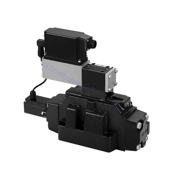
Katup Hidraulik Arah Proporsional yang Dioperasikan Pilot Seri 4WRLE
Katup Hidraulik Arah Proporsional yang Dioperasikan Pilot Seri 4WRLE
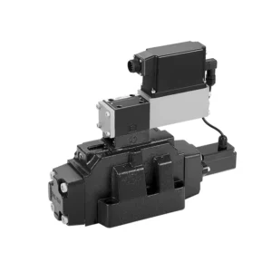
Katup hidrolik proporsional arah yang dioperasikan pilot seri 4WRLE adalah komponen hidrolik mutakhir yang merevolusi kontrol fluida dalam sistem hidrolik. Katup ini menggabungkan teknologi yang dioperasikan pilot dengan kontrol arah proporsional, menawarkan pengaturan aliran yang presisi dan efisiensi yang luar biasa.
Katup hidrolik proporsional arah yang dioperasikan pilot seri 4WRLE meningkatkan kontrol hidrolik ke tingkat presisi dan efisiensi yang baru. Dengan teknologi pengoperasian pilot dan kontrol arah proporsionalnya, katup ini memastikan pengaturan aliran yang akurat, konsumsi energi yang optimal, dan peningkatan kinerja sistem. Dengan mengikuti metode penggunaan dan panduan perawatan yang direkomendasikan, Anda dapat memaksimalkan potensi penuh katup seri 4WRLE dan mencapai kontrol hidrolik yang unggul. Tingkatkan sistem hidrolik Anda hari ini dan rasakan kekuatan presisi dengan katup hidrolik proporsional arah yang dioperasikan pilot seri 4WRLE.
Karakteristik Utama Katup Hidraulik Arah Proporsional yang Dioperasikan Pilot Seri 4WRLE:
- Teknologi yang Dioperasikan Pilot:
- Katup seri 4WRLE menggabungkan teknologi pengoperasian pilot, memungkinkan kontrol aliran fluida dan pengaturan tekanan yang presisi.
- Teknologi ini memungkinkan penggunaan energi yang efisien dan mengurangi produksi panas, sehingga menghasilkan peningkatan kinerja sistem secara keseluruhan dan mengurangi biaya operasional.
- Kontrol Arah Proporsional:
- Dengan kemampuan kontrol arah proporsionalnya, katup ini memberikan penyesuaian aliran yang akurat dan seimbang berdasarkan sinyal kontrol.
- Kontrol proporsional memungkinkan pengendalian aktuator hidrolik yang halus dan presisi, meningkatkan kinerja sistem dan meminimalkan keausan.
- Fungsionalitas Serbaguna:
- Katup seri 4WRLE menawarkan kontrol serbaguna atas arah aliran fluida, sehingga cocok untuk berbagai aplikasi hidrolik.
- Baik itu untuk mengontrol silinder, motor, atau komponen hidrolik lainnya, katup ini memastikan aktivasi dan deaktivasi yang mulus dalam berbagai arah, meningkatkan fleksibilitas dan kemampuan adaptasi sistem.
- Kapasitas Aliran Tinggi:
- Dirancang untuk menangani laju aliran tinggi, katup seri 4WRLE memberikan kinerja luar biasa bahkan dalam aplikasi yang menuntut.
- Konstruksinya yang kokoh dan saluran aliran yang dioptimalkan memastikan pengoperasian yang andal dan kontrol aliran yang konsisten, memenuhi persyaratan sistem hidrolik daya tinggi.
Parameter Katup Hidraulik Arah Proporsional yang Dioperasikan Pilot Seri 4WRLE:
NG6
| Umum | |||||||
| Desain | Katup spool, dioperasikan langsung, dengan selongsong baja. | ||||||
| Aktuasi | Solenoid proporsional dengan kontrol posisi, OBE | ||||||
| Jenis koneksi | Pemasangan pelat dasar, pola porting sesuai dengan ISO 4401-03-02-0-05 | ||||||
| Posisi pemasangan | Setiap | ||||||
| Kisaran suhu sekitar | ℃ | -20…+50 | |||||
| Berat | kg | sekitar 2,75 | |||||
| Ketahanan getaran maksimum (kondisi pengujian) | Maks. 25 g, uji getaran ruang angkasa ke segala arah (24 jam) | ||||||
| Hidrolik (diukur pada p=100 bar, dengan HLP46 pada ϑoil = 40℃ ±5℃) | |||||||
| Fluida bertekanan | Minyak mineral (HL, HLP) sesuai DIN 51 524 | ||||||
| Kisaran viskositas | direkomendasikan | mm²/detik | 20…100 | ||||
| maks. yang diizinkan | mm²/detik | 10…800 | |||||
| Kisaran suhu fluida tekanan | ℃ | -20 hingga +70 | |||||
| Tingkat kontaminasi maksimum yang diizinkan dari cairan bertekanan Kelas kemurnian menurut ISO 4406 (c) | Kelas 18/16/13 | ||||||
| Aliran nominal (Δp = 35 bar per sisi) | L/menit | 2 | 4 | 12 | 24 | 40 | |
| Tekanan operasi maks. | batang | Pelabuhan A, B, P: 315 | |||||
| Tekanan maksimum | batang | Pelabuhan T: 250 | |||||
| Aliran kebocoran pada 100 bar | Linier | cm³/menit | <150 | <180 | <300 | <500 | <900; |
| Nonlinier | cm³/menit | / | / | / | <300 | <450; | |
| Statis/Dinamis | |||||||
| Histeresis | % | ≤0,2 | |||||
| Waktu aktivasi untuk langkah sinyal 0 … 100% | MS | 10 | |||||
| Pergeseran suhu | Pergeseran nol < 1% pada ΔT=40℃ | ||||||
| Tidak ada kompensasi sama sekali | Dari pabrik ±1% | ||||||
| Elektronik kontrol listrik terintegrasi dalam katup. | |||||||
| Siklus kerja relatif | % | 100ED | |||||
| Tingkat perlindungan | IP65 | ||||||
| Koneksi | Konektor plug-in 6P+PE, DIN 43563 | ||||||
| Tegangan suplai Terminal A Terminal B |
24VDCnom | ||||||
| min. 21VDC / maks. 40VDC | |||||||
| 0V (riak maks. 2) | |||||||
| Perlindungan sekering, eksternal | AF | 2.5 | |||||
| input, versi “A1” Terminal D (UE) Terminal E |
Penguat diferensial, Ri = 100 kΩ | ||||||
| 0…±10V | |||||||
| 0V | |||||||
| Input, versi “F1” Terminal D (ID-E) Terminal E (ID-E) |
Muat, Rsh = 200 Ω | ||||||
| 4…12…20mA | |||||||
| Loop arus IDE kembali | |||||||
| Sinyal uji, versi “A1” Terminal F (Tes U) Terminal C |
LVDT | ||||||
| 0…±10V | |||||||
| Referensi 0 V | |||||||
| Sinyal uji, versi “F1” Terminal F ( I FC ) Terminal C ( I FC ) |
Sinyal LVDT 4 … (12) … 20 mA pada beban eksternal 200 … 500 Ω maksimum | ||||||
| 4 … (12) … 20mA (keluaran) | |||||||
| Loop arus IFC kembali | |||||||
| Pengaturan | Dikaliibrasi sebelum pengiriman, lihat kurva karakteristik. | ||||||
NG10
| Umum | |||||
| Desain | Katup spool, dioperasikan langsung, dengan selongsong baja. | ||||
| Aktuasi | Solenoid proporsional dengan kontrol posisi, OBE | ||||
| Jenis koneksi | Port pelat, pola porting (ISO 4401-05-04-0-05) | ||||
| Posisi pemasangan | Setiap | ||||
| Kisaran suhu keadaan | ℃ | -20…+50 | |||
| Berat | kg | sekitar 7.1 | |||
| Ketahanan getaran maksimum (kondisi pengujian) | Maks. 25 g, uji getaran ruang angkasa ke segala arah (24 jam) | ||||
| Hidraulik (diukur dengan HLP 46, ϑoil =40℃ ±5℃) | |||||
| Fluida bertekanan | Oli hidrolik sesuai dengan DIN 51524…535 | ||||
| Kisaran viskositas | direkomendasikan | mm²/detik | 20…100 | ||
| Maksimum yang diizinkan | mm²/detik | 10…800 | |||
| Kisaran suhu fluida tekanan | ℃ | -20 hingga +70 | |||
| Tingkat kontaminasi maksimum yang diizinkan pada cairan hidrolik, kelas kebersihan menurut ISO 4406 (c) | Kelas 18/16/13 | ||||
| Aliran nominal (Δp = 35 bar per sisi) | L/menit | 50 | 100 | ||
| Tekanan operasi maks. | batang | Port PAB: 315 | |||
| Tekanan maksimum | batang | Pelabuhan T: 250 | |||
| Aliran kebocoran pada 100 bar | Linier | cm³/menit | <1200 | <1500 | |
| Nonlinier | cm³/menit | <600 | <600 | ||
| Statis/Dinamis | |||||
| Histeresis | % | ≤0,2 | |||
| Waktu aktivasi untuk langkah sinyal 0 … 100% | MS | 25 | |||
| Pergeseran suhu | Pergeseran nol < 1% pada ΔT=40℃ | ||||
| Tidak ada kompensasi sama sekali | Dari pabrik ±1% | ||||
| Elektronik kontrol listrik terintegrasi dalam katup. | |||||
| Siklus kerja relatif | % | 100ED | |||
| Tingkat perlindungan | IP65 (dengan konektor penghubung terpasang dan terkunci) | ||||
| Koneksi | Konektor kawin 6P+PE, DIN 43563 | ||||
| Tegangan suplai Terminal A Terminal B |
24VDCnom | ||||
| min. 21VDC / maks. 40VDC | |||||
| Riak maksimum 2 VDC | |||||
| Perlindungan sekering, eksternal | AF | 2.5 | |||
| Masukan, versi “A1” Terminal D (UE) Terminal E |
Penguat diferensial, Ri = 100 kΩ | ||||
| 0…±10V | |||||
| 0V | |||||
| Input, versi “F1” Terminal D (IDE) Terminal E (IDE) |
Muat, Rsh = 200 | ||||
| 4…12…20mA | |||||
| Loop arus IDE kembali | |||||
| Sinyal uji, versi “A1” Terminal F (UTes) Terminal C |
LVDT | ||||
| 0…±10V | |||||
| Referensi 0 V | |||||
| Sinyal uji, versi “F1” Terminal F ( I FC ) Terminal C ( I FC ) |
LVDT | ||||
| Keluaran 4…20 mA | |||||
| Loop arus IFC masukan | |||||
Keunggulan Katup Hidraulik Arah Proporsional yang Dioperasikan Pilot Seri 4WRLE:
• Katup solenoid servo kerja langsung dengan piston kontrol dan selongsong katup, dengan kinerja servo
• Penggerak satu sisi, opsional, dengan fungsi keselamatan mati daya
Solenoid kontrol dengan umpan balik bawaan dan papan penguat terintegrasi (OBE), pengaturan pabrik.
• Koneksi listrik penguat diferensial input sinyal 6P+PE dengan antarmuka, input opsional A1: ±10V, atau antarmuka F1: 4…20mA (Rsh =200Ω)
• Pemasangan panel: permukaan pemasangan sesuai dengan ISO 4401-03-02
Metode Penggunaan Katup Hidrolik Arah Proporsional yang Dioperasikan Pilot Seri 4WRLE:
- Penilaian Sistem:
- Evaluasi sistem hidrolik Anda dan tentukan persyaratan kontrol aliran dan arah yang spesifik.
- Identifikasi apakah katup seri 4WRLE kompatibel dengan sistem Anda berdasarkan faktor-faktor seperti kapasitas aliran, peringkat tekanan, dan kompatibilitas dengan aplikasi Anda.
- Pemilihan Katup:
- Pilih varian katup seri 4WRLE yang sesuai berdasarkan parameter sistem, kebutuhan aliran, dan kebutuhan kontrol arah Anda.
- Pertimbangkan faktor-faktor seperti laju aliran maksimum, peringkat tekanan, waktu respons, dan kondisi operasi lingkungan.
- Instalasi:
- Ikuti petunjuk pemasangan dari pabrikan dengan cermat untuk memastikan penyelarasan yang tepat dan pemasangan katup yang aman.
- Buat sambungan yang kedap bocor dan pastikan arah aliran yang tepat untuk menjamin kinerja optimal.
- Integrasi Sinyal Kontrol:
- Hubungkan kabel sinyal kontrol katup ke perangkat kontrol yang sesuai, seperti penguat proporsional atau unit kontrol elektronik.
- Pastikan pemasangan kabel yang tepat dan kompatibilitas antara katup dan perangkat kontrol untuk mencapai kontrol yang akurat dan responsif.
Bagaimana Cara Memasang Katup Kontrol Aliran Hidrolik?
Untuk memasang katup kontrol aliran hidrolik, ikuti langkah-langkah berikut:
- Identifikasi Jenis Katup: Tentukan jenis katup kontrol aliran yang Anda gunakan. Jenis yang umum digunakan antara lain katup jarum, katup kontrol aliran yang dapat disesuaikan, atau katup kontrol aliran dengan kompensasi tekanan. Pastikan katup tersebut sesuai dengan aplikasi Anda dan kompatibel dengan sistem hidrolik Anda.
- Kumpulkan Alat dan Bahan yang Diperlukan: Kumpulkan peralatan dan bahan yang diperlukan, termasuk perlengkapan hidrolik, adaptor, selang, dan kunci pas yang sesuai.
- Siapkan Sistem Hidrolik: Matikan sistem hidrolik dan kurangi tekanan dalam sistem dengan mengaktifkan katup pelepas atau menarik silinder hidrolik. Langkah ini penting untuk keselamatan.
- Identifikasi Arah Aliran: Identifikasi arah aliran dalam sistem hidrolik Anda. Biasanya, arah aliran ditunjukkan oleh tanda panah pada komponen hidrolik. Pastikan Anda memahami arah aliran yang benar sebelum melanjutkan.
- Temukan Titik Instalasi: Tentukan lokasi optimal untuk memasang katup kontrol aliran pada sistem hidrolik Anda. Pertimbangkan faktor-faktor seperti aksesibilitas, kedekatan dengan aktuator atau komponen hidrolik, dan kemudahan penyesuaian.
- Pasang Katup: Pasang katup pengatur aliran dengan aman di lokasi yang dipilih menggunakan braket atau klem yang sesuai. Pastikan katup diposisikan dengan benar, sejajarkan lubang masuk dan keluar dengan arah aliran.
- Hubungkan Port Masuk dan Keluar: Pasang selang atau pipa hidrolik ke port masuk dan keluar katup kontrol aliran. Gunakan fitting dan adaptor hidrolik yang sesuai untuk memastikan sambungan bebas kebocoran. Kencangkan sambungan menggunakan kunci inggris untuk memastikan sambungan terpasang dengan benar, tetapi hindari mengencangkannya terlalu kencang.
- Sesuaikan Kontrol Aliran: Tergantung pada jenis katup pengontrol aliran, katup tersebut mungkin memiliki fitur yang dapat disesuaikan seperti katup jarum atau kenop pengontrol aliran. Sesuaikan katup sesuai dengan laju atau kecepatan aliran yang Anda inginkan. Lihat petunjuk produsen untuk prosedur penyesuaian spesifik.
- Uji Sistem: Setelah katup kontrol aliran dipasang dan disetel, kembalikan tekanan sistem hidrolik secara perlahan. Uji sistem untuk memastikan katup kontrol aliran berfungsi dengan benar. Pantau laju aliran atau kecepatan aktuator hidrolik untuk memastikannya berada dalam rentang yang diinginkan.
- Penyetelan halus dan pantau: Sesuaikan katup kontrol aliran untuk mencapai laju atau kecepatan aliran yang diinginkan. Pantau sistem hidrolik secara berkala untuk mendeteksi kebocoran, ketidakkonsistenan tekanan, atau perilaku yang tidak biasa.
Kemampuan & Kapasitas Pabrik:
(1) Perakitan
Kami memiliki platform perakitan penelitian dan pengembangan independen kelas satu. Bengkel produksi silinder hidrolik memiliki empat jalur perakitan silinder pengangkat semi-otomatis dan satu jalur perakitan silinder kemiringan otomatis, dengan kapasitas produksi tahunan yang dirancang sebesar 1 juta keping. Bengkel silinder khusus dilengkapi dengan berbagai spesifikasi sistem perakitan pembersihan semi-otomatis dengan kapasitas produksi tahunan yang dirancang sebesar 200.000 dan dilengkapi dengan peralatan permesinan CNC yang terkenal, pusat permesinan, peralatan khusus pemrosesan silinder presisi tinggi, mesin las robot, mesin pembersih otomatis, mesin perakitan silinder otomatis, dan jalur produksi pengecatan otomatis. Peralatan penting yang ada lebih dari 300 set (set). Alokasi optimal dan penggunaan sumber daya peralatan yang efisien memastikan persyaratan akurasi produk dan memenuhi kebutuhan produk berkualitas tinggi.


(2) Pemesinan
Bengkel permesinan dilengkapi dengan pusat pembubutan rel miring yang disesuaikan, pusat permesinan, mesin pengasah berkecepatan tinggi, robot pengelasan, dan peralatan terkait lainnya, yang dapat menangani pemrosesan tabung silinder dengan diameter bagian dalam maksimum 400mm dan panjang maksimum 6 meter.

(3) Pengelasan

(4) Pengecatan & pelapisan
Dengan jalur pelapisan cat berbasis air otomatis silinder kecil dan menengah, untuk mencapai bongkar muat robot otomatis dan penyemprotan otomatis, kapasitas desain 4000 buah per shift;
Kami juga memiliki lini produksi cat semi-otomatis untuk silinder besar yang ditenagai oleh rantai daya, dengan kapasitas desain 60 kasus per shift.


(5) Pengujian
Kami memiliki fasilitas inspeksi kelas satu dan test bed untuk memastikan bahwa kinerja silinder memenuhi persyaratan.

Kami adalah salah satu produsen silinder hidrolik terbaik. Kami dapat menawarkan silinder hidrolik yang lengkap. Kami juga menyediakan produk yang sesuai. gearbox pertanian. Kami telah mengekspor produk kami ke klien di seluruh dunia dan mendapatkan reputasi yang baik karena kualitas produk dan layanan purna jual kami yang unggul. Kami menyambut pelanggan di dalam dan luar negeri untuk menghubungi kami untuk menegosiasikan bisnis, bertukar informasi, dan bekerja sama dengan kami!


