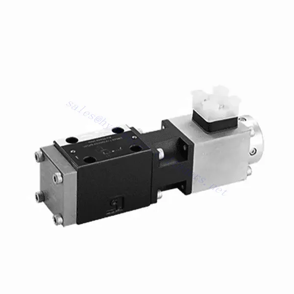
Katup Hidrolik Pelepas Tekanan Proporsional Seri DBE6X(E)
Sebagai salah satu produsen, pemasok, dan eksportir silinder hidrolik, Kami menawarkan silinder hidrolik dan banyak produk lainnya.
Silakan hubungi kami untuk informasi lebih lanjut.
Surat:sales@hydraulic-cylinders.net
Produsen pemasok eksportir silinder hidrolik.
Katup Hidrolik Pelepas Tekanan Proporsional Seri DBE6X(E)
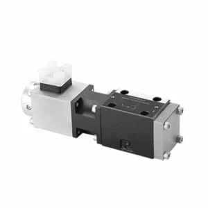
Katup hidrolik pelepas tekanan proporsional seri DBE6X(E) adalah komponen mutakhir yang memberikan kontrol tekanan yang akurat dan dinamis dalam sistem hidrolik. Dengan teknologi kontrol proporsional canggihnya, katup ini memastikan kinerja, efisiensi, dan keamanan yang optimal.
Katup hidrolik pelepas tekanan proporsional seri DBETX memberikan sistem hidrolik kontrol tekanan yang presisi, efisiensi yang ditingkatkan, dan perlindungan peralatan. Dengan kemampuan pelepas tekanan yang sesuai, katup ini memastikan kinerja optimal di berbagai aplikasi. Dengan mengikuti metode penggunaan dan panduan perawatan yang direkomendasikan, Anda dapat memaksimalkan manfaat dan keandalan katup seri DBETX, meningkatkan kinerja dan kontrol sistem hidrolik Anda. Tingkatkan pengaturan hidrolik Anda hari ini dan rasakan pengaturan tekanan yang unggul dengan katup hidrolik pelepas tekanan proporsional seri DBETX.
Karakteristik Utama Katup Hidrolik Pelepas Tekanan Proporsional Seri DBE6X(E):
- Pengurangan Tekanan Proporsional:
- Katup seri DBE6X(E) menawarkan pelepasan tekanan yang presisi dan proporsional, memungkinkan kontrol tekanan hidrolik dinamis.
- Hal ini memastikan pengaturan tekanan yang akurat sebagai respons terhadap kondisi beban yang bervariasi, mencegah kelebihan beban sistem, dan melindungi komponen hidrolik.
- Peningkatan Efisiensi Sistem:
- Katup ini memungkinkan kontrol tekanan hidrolik yang presisi, sehingga meningkatkan efisiensi sistem dan mengurangi konsumsi energi.
- Dengan mempertahankan tingkat tekanan yang diinginkan, hal ini meminimalkan fluktuasi tekanan, mengoptimalkan kinerja sistem, dan mengurangi biaya operasional.
- Keselamatan dan Perlindungan Peralatan:
- Katup Seri DBE6X(E) bertindak sebagai mekanisme pelindung dengan membatasi tekanan di dalam sistem hidrolik, sehingga melindungi peralatan dan operator.
- Hal ini mencegah penumpukan tekanan berlebihan, mengurangi risiko kerusakan komponen, kegagalan sistem, dan potensi kecelakaan.
- Fungsi Kontrol Proporsional:
- Dengan teknologi kontrol proporsionalnya, katup seri DBE6X(E) menawarkan penyesuaian tekanan yang halus dan presisi.
- Ini memungkinkan kontrol tekanan secara real-time, sehingga memungkinkan integrasi yang mulus ke dalam berbagai sistem dan aplikasi hidrolik.
Parameter Katup Hidrolik Pelepas Tekanan Proporsional Seri DBE6X(E):
| Umum | ||||||
| Konstruksi | Tahap percontohan | Katup poppet | ||||
| Panggung utama | Katup spul | |||||
| Aktuasi | Solenoid proporsional tanpa kontrol posisi, penguat eksternal | |||||
| Jenis koneksi | Subplate, konfigurasi lubang pemasangan NG6 (SIO 4401-03-02-094) | |||||
| Posisi pemasangan | Opsional | |||||
| Kisaran suhu keadaan | ℃ | -20 hingga +50 | ||||
| Berat | kg | 2.2 | ||||
| Ketahanan getaran, kondisi uji | Maks. 25 g, dikocok dalam 3 dimensi (24 jam) | |||||
| Hidrolik (diukur dengan HLP 46, oli = 40℃ ±5℃): | ||||||
| Fluida bertekanan | Oli hidrolik sesuai standar DIN 51524…535, cairan lain setelah konsultasi terlebih dahulu. | |||||
| Kisaran viskositas | direkomendasikan | mm²/detik | 20…100 | |||
| maks. yang diizinkan | mm²/detik | 10…800 | ||||
| Kisaran suhu fluida tekanan | ℃ | -20 hingga +80 | ||||
| Tingkat kontaminasi maksimum yang diizinkan dari cairan bertekanan Kelas kemurnian menurut ISO 4406 (c) | Kelas 18/16/13 | |||||
| Arah aliran | Lihat simbol | |||||
| Tekanan pengaturan maks. (pada Qmaxx = 1 L/menit) | batang | 80 | 180 | 250 | 315 | |
| Minimal. tekanan yang dapat diatur(当 Qmin = 1 L/mnt) | batang | 7 | 8 | 9 | 10 | |
| Tekanan operasi maks. | batang | Pelabuhan P:315 | ||||
| Pelabuhan T:250 | ||||||
| Batasan tekanan mekanis maks., misalnya saat arus solenoid I>Imax | batang | < 90 | < 190 | < 260 | < 235 | |
| Aliran oli pilot | L/menit | sekitar 0,6 | ||||
| Laju aliran maks. | L/menit | 40 | ||||
| Data listrik | ||||||
| Faktor durasi siklik | % | 100 ED | ||||
| Tingkat perlindungan | IP 65 hingga DIN 40050 dan IEC 14434/5 | |||||
| Koneksi solenoida | Konektor plug-in ke DIN 43650/ISO 4400, M16X1.5(2P+PE) | |||||
| Katup dengan tipe solenoid | 0,8A | 2.5A | ||||
| Arus solenoid maks. | Imax | 0,8A | 2.5A | |||
| Resistansi kumparan R20 | Ω | 22 | 3 | |||
| Konsumsi daya maks. pada beban 100% dan suhu pengoperasian | VA | 25 | 30 | |||
| Statis/Dinamis | ||||||
| Histeresis | % | ≤ 4 | ||||
| Rentang inversi | % | ≤3 | ||||
| Toleransi manufaktur untuk Pmax | % | ≤10 | ||||
| Waktu respons perubahan sinyal 100% | MS | Aktif 200 / Nonaktif | ||||
Keunggulan Katup Hidrolik Pelepas Tekanan Proporsional Seri DBE6X(E):
• Katup pilot untuk membatasi tekanan sistem (hanya mengontrol oli internal)
• Dapat menyesuaikan dengan mengendalikan arus kumparan sesuai dengan kurva karakteristik dan unit kontrol elektronik yang dipilih
• Tipe solenoid Imax = 0,8 A atau 2,5 A
• Jika terjadi kegagalan unit kontrol elektronik, proteksi kelebihan beban dapat berfungsi pada tingkat tertinggi (arus kumparan > Imax)
• Digunakan pada pemasangan sub-pelat katup, lubang pemasangan mengikuti ISO 441-03-02-0-94,
• Soket kabel mengikuti DIN 43650-AM2
• Unit kontrol elektronik eksternal dengan fungsi penyesuaian ramp dan katup VT-SSPA1-508/525-L2X/V0/*
Metode Penggunaan Katup Hidrolik Pelepas Tekanan Proporsional Seri DBE6X(E):
- Evaluasi Sistem:
- Evaluasi sistem hidrolik Anda dan identifikasi persyaratan pengendalian tekanan spesifiknya.
- Tentukan apakah katup seri DBE6X(E) kompatibel dengan sistem Anda berdasarkan rentang tekanan, kapasitas aliran, dan spesifikasi lainnya.
- Pemilihan Katup:
- Pilih varian katup seri DBE6X(E) yang sesuai berdasarkan parameter sistem, rentang tekanan, dan kebutuhan aliran Anda.
- Pertimbangkan peringkat tekanan maksimum, waktu respons, dan kondisi operasional.
- Instalasi:
- Ikuti petunjuk pemasangan dari pabrikan dengan cermat, pastikan penyelarasan yang tepat dan pemasangan katup yang aman.
- Hubungkan katup ke sistem hidrolik, pastikan sambungan tidak bocor dan arah aliran sejajar dengan benar.
- Penyesuaian Tekanan:
- Gunakan sinyal kontrol proporsional atau mekanisme penyesuaian yang disediakan pada katup seri DBE6X(E) untuk mengatur tingkat pelepasan tekanan yang diinginkan.
- Sesuaikan katup secara bertahap, pantau pembacaan pengukur tekanan dan respons sistem untuk mencapai kontrol tekanan yang tepat.
Bagaimana Cara Menyetel Katup Pengontrol Aliran Hidrolik?
Menyetel katup pelepas tekanan hidrolik memungkinkan Anda untuk mengatur tekanan maksimum yang diinginkan dalam sistem hidrolik. Hal ini penting untuk menjaga integritas sistem dan mencegah kerusakan pada komponen. Berikut panduan langkah demi langkah tentang cara menyetel katup pelepas tekanan hidrolik:
- Identifikasi Katup Pelepas Tekanan:
- Cari katup pelepas tekanan di sistem hidrolik Anda. Biasanya terpasang di saluran hidrolik dan seringkali dekat dengan pompa atau katup kontrol.
- Pahami Desain Katup:
- Pahami desain spesifik dari katup pelepas tekanan yang Anda gunakan. Katup yang berbeda mungkin memiliki mekanisme penyetelan yang berbeda, seperti kenop, sekrup, atau mur pengunci.
- Tentukan Tekanan yang Diinginkan:
- Nilailah kebutuhan sistem hidrolik Anda dan tentukan tekanan maksimum yang diinginkan. Hal ini akan memandu Anda dalam menyesuaikan katup pelepas tekanan secara akurat.
- Siapkan Sistem:
- Sebelum melakukan penyesuaian apa pun, matikan sistem hidrolik dan kurangi tekanan dengan menggerakkan tuas kontrol maju mundur atau mengikuti prosedur yang direkomendasikan oleh pabrikan.
- Temukan Mekanisme Penyesuaian:
- Identifikasi mekanisme penyetelan pada katup pelepas tekanan. Mekanisme tersebut bisa berupa kenop, sekrup, atau mur pengunci yang terletak pada badan katup atau di dekatnya.
- Sesuaikan Katup:
- Jika katup memiliki kenop atau pegangan, putar searah jarum jam untuk meningkatkan pengaturan pelepas tekanan atau berlawanan arah jarum jam untuk menurunkannya. Jika katup memiliki sekrup, putar searah jarum jam untuk meningkatkan pelepas tekanan atau berlawanan arah jarum jam untuk menurunkannya.
- Lakukan Penyesuaian Bertahap:
- Saat menyetel katup pelepas tekanan, lakukan perubahan kecil secara bertahap untuk menghindari variasi tekanan yang tiba-tiba atau drastis. Hal ini memungkinkan Anda untuk menyempurnakan tekanan maksimum dan mencapai kinerja yang diinginkan.
- Amati Sistemnya:
- Pada setiap penyetelan, amati sistem hidrolik dan komponen-komponennya. Perhatikan pembacaan pengukur tekanan untuk melihat apakah sesuai dengan tekanan maksimum yang diinginkan.
- Uji dan Verifikasi:
- Operasikan sistem hidrolik dan pantau tekanannya untuk memastikan tekanan tetap berada dalam kisaran yang diinginkan. Periksa fluktuasi atau ketidaknormalan tekanan yang mungkin mengindikasikan perlunya penyesuaian lebih lanjut.
- Kunci Pengaturan:
- Setelah Anda mencapai pengaturan pelepasan tekanan yang diinginkan, kencangkan mekanisme penyetelan untuk mencegah perubahan yang tidak disengaja. Beberapa katup mungkin memiliki mur pengunci atau sekrup penyetel yang dapat dikencangkan untuk menahan penyetelan pada tempatnya.
- Pantau dan Tinjau Kembali:
- Pantau katup pelepas tekanan dan sistem hidrolik secara berkala. Jika ada perubahan pada sistem atau jika tekanan maksimum yang diinginkan perlu disesuaikan, periksa kembali katup pelepas tekanan dan ulangi proses penyesuaian sesuai kebutuhan.
Kemampuan & Kapasitas Pabrik:
(1) Perakitan
Kami memiliki platform perakitan penelitian dan pengembangan independen kelas satu. Bengkel produksi silinder hidrolik memiliki empat jalur perakitan silinder pengangkat semi-otomatis dan satu jalur perakitan silinder kemiringan otomatis, dengan kapasitas produksi tahunan yang dirancang sebesar 1 juta keping. Bengkel silinder khusus dilengkapi dengan berbagai spesifikasi sistem perakitan pembersihan semi-otomatis dengan kapasitas produksi tahunan yang dirancang sebesar 200.000 dan dilengkapi dengan peralatan permesinan CNC yang terkenal, pusat permesinan, peralatan khusus pemrosesan silinder presisi tinggi, mesin las robot, mesin pembersih otomatis, mesin perakitan silinder otomatis, dan jalur produksi pengecatan otomatis. Peralatan penting yang ada lebih dari 300 set (set). Alokasi optimal dan penggunaan sumber daya peralatan yang efisien memastikan persyaratan akurasi produk dan memenuhi kebutuhan produk berkualitas tinggi.


(2) Pemesinan
Bengkel permesinan dilengkapi dengan pusat pembubutan rel miring yang disesuaikan, pusat permesinan, mesin pengasah berkecepatan tinggi, robot pengelasan, dan peralatan terkait lainnya, yang dapat menangani pemrosesan tabung silinder dengan diameter bagian dalam maksimum 400mm dan panjang maksimum 6 meter.

(3) Pengelasan

(4) Pengecatan & pelapisan
Dengan jalur pelapisan cat berbasis air otomatis silinder kecil dan menengah, untuk mencapai bongkar muat robot otomatis dan penyemprotan otomatis, kapasitas desain 4000 buah per shift;
Kami juga memiliki lini produksi cat semi-otomatis untuk silinder besar yang ditenagai oleh rantai daya, dengan kapasitas desain 60 kasus per shift.


(5) Pengujian
Kami memiliki fasilitas inspeksi kelas satu dan test bed untuk memastikan bahwa kinerja silinder memenuhi persyaratan.

Kami adalah salah satu produsen silinder hidrolik terbaik. Kami dapat menawarkan silinder hidrolik yang lengkap. Kami juga menyediakan produk yang sesuai. gearbox pertanian. Kami telah mengekspor produk kami ke klien di seluruh dunia dan mendapatkan reputasi yang baik karena kualitas produk dan layanan purna jual kami yang unggul. Kami menyambut pelanggan di dalam dan luar negeri untuk menghubungi kami untuk menegosiasikan bisnis, bertukar informasi, dan bekerja sama dengan kami!
Aplikasi Silinder Hidraulik:
