

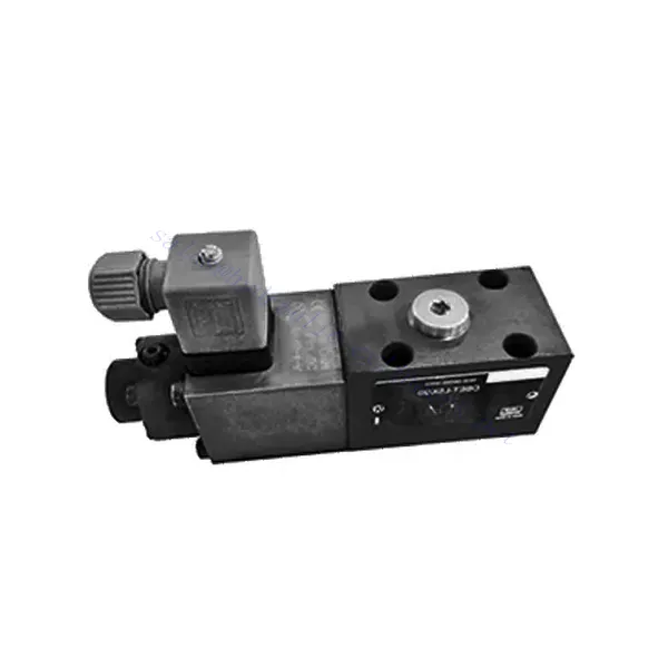
Katup Hidrolik Pelepas Tekanan Proporsional Seri DBET(E)
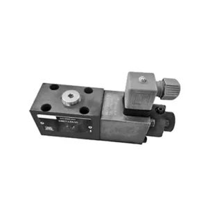

Katup hidrolik pelepas tekanan proporsional seri DBET(E) adalah komponen mutakhir yang dirancang untuk memberikan kontrol tekanan yang presisi dalam sistem hidrolik. Dengan teknologi kontrol proporsional canggih dan kinerja luar biasa, katup ini mengoptimalkan efisiensi sistem, meningkatkan keselamatan, dan memperpanjang umur peralatan hidrolik.
Katup hidrolik pelepas tekanan proporsional seri DBET(E) merupakan komponen yang sangat penting untuk mencapai kontrol tekanan yang presisi dalam sistem hidrolik. Dengan pengaturan tekanan proporsional, efisiensi yang ditingkatkan, dan fitur perlindungan peralatan, katup ini mengoptimalkan kinerja sistem sekaligus memastikan keamanan dan umur panjang peralatan hidrolik. Dengan mengikuti metode penggunaan dan panduan perawatan yang direkomendasikan, Anda dapat memanfaatkan potensi penuh katup hidrolik pelepas tekanan proporsional seri DBET(E), memaksimalkan kinerja dan keandalan sistem hidrolik Anda. Tingkatkan pengaturan hidrolik Anda hari ini dan rasakan kontrol tekanan optimal dengan katup seri DBET(E).
Karakteristik Utama Katup Hidrolik Pelepas Tekanan Proporsional Seri DBET(E):
- Kontrol Tekanan Proporsional:
- Katup seri DBET(E) menawarkan pelepasan tekanan yang presisi dan proporsional, memungkinkan pengaturan tekanan yang akurat dan dinamis dalam sistem hidrolik.
- Sistem ini mempertahankan tingkat tekanan yang konsisten terhadap beban yang bervariasi, memastikan kinerja optimal dan mencegah kerusakan pada komponen hidrolik.
- Peningkatan Efisiensi Sistem:
- Dengan menyediakan kontrol tekanan proporsional, katup ini membantu mengoptimalkan efisiensi sistem dengan mengurangi konsumsi energi dan meminimalkan fluktuasi tekanan.
- Hal ini memastikan bahwa peralatan hidrolik beroperasi pada tekanan yang diinginkan, sehingga menghasilkan peningkatan produktivitas dan pengurangan biaya operasional.
- Keselamatan dan Perlindungan Peralatan:
- Katup Seri DBET(E) berfungsi sebagai tindakan pengamanan dengan membatasi tekanan dalam sistem hidrolik, mencegah kelebihan beban dan potensi kerusakan pada peralatan atau operator.
- Ini melindungi komponen sensitif dari tekanan berlebihan, memperpanjang masa pakainya, dan mengurangi risiko kegagalan sistem.
- Fleksibilitas dan Kemampuan Beradaptasi:
- Katup ini tersedia dalam berbagai ukuran dan rentang tekanan, sehingga kompatibel dengan berbagai sistem dan aplikasi hidrolik.
- Desainnya yang mudah disesuaikan membuatnya cocok untuk berbagai industri, termasuk manufaktur, konstruksi, pertanian, dan banyak lagi.
Parameter Katup Hidrolik Pelepas Tekanan Proporsional Seri DBET(E):
| Cairan | Oli mineral cocok untuk seal NBR dan FKM | |
| Ester fosfat untuk segel FKM | ||
| Kisaran suhu fluida | ℃ | -30 hingga +80 (segel NBR) |
| -20 hingga +80 (segel FKM) | ||
| Kisaran viskositas | mm2/S | 15 sampai 380 |
| Tingkat kontaminasi | Tingkat kontaminasi cairan maksimum yang diperbolehkan: Kelas 9 dan ISO4406 Kelas 20/18/15 | |
| Tekanan operasi maksimum (Port P) | batang | 350 |
| Tekanan pengaturan maks. | batang | 50; 100; 200; 315; 350 |
| Tekanan minimum yang dapat diatur | Lihat kurva karakteristik | |
| Tekanan minimum yang dapat diatur pada nilai perintah 0 | = Tekanan minimum yang dapat diatur | |
| Tekanan balik (Port T) | batang | Terpisah dan pada tekanan nol ke tangki |
| Laju aliran maks. | L/menit | 2 |
| Linearitas | ± 3,5 % dari tekanan maksimum yang dapat diatur | |
| Histeresis | ± 1,5 % dari tekanan maksimum yang dapat diatur | |
| Pengulangan | < ± 2 % dari tekanan maksimum yang dapat diatur | |
| Waktu peralihan | MS | 30 hingga 150 (tergantung sistem) |
Keunggulan Katup Hidrolik Pelepas Tekanan Proporsional Seri DBET(E):
• Langsung, untuk membatasi tekanan sistem
• Permukaan pemasangan sesuai dengan ISO 4401-03-02-0-05
• Lima rentang tekanan
• Amplifier elektronik pendamping VT-2000 atau amplifier plug-in VT-SSPA1-…-L2X (pesanan terpisah)
Metode Penggunaan Katup Hidrolik Pelepas Tekanan Proporsional Seri DBET(E) :
- Evaluasi Sistem:
- Evaluasilah persyaratan spesifik sistem hidrolik Anda, termasuk rentang tekanan yang diinginkan, laju aliran maksimum, dan kompatibilitas dengan komponen yang sudah ada.
- Tentukan apakah katup seri DBET(E) sesuai dengan aplikasi Anda berdasarkan kemampuan pengendalian tekanannya dan kompatibilitasnya dengan sistem Anda.
- Pemilihan Katup:
- Pilih varian katup seri DBET(E) yang sesuai berdasarkan parameter sistem Anda, rentang tekanan yang dibutuhkan, dan kapasitas aliran.
- Pertimbangkan peringkat tekanan maksimum, waktu respons, dan kondisi operasional.
- Instalasi:
- Follow the manufacturer’s installation instructions carefully, ensuring proper alignment and secure valve mounting.
- Hubungkan katup ke sistem hidrolik, perhatikan indikator arah aliran dan pastikan sambungan tidak bocor.
- Pengaturan Tekanan:
- Sesuaikan pengaturan pelepas tekanan katup agar sesuai dengan rentang tekanan yang diinginkan untuk aplikasi Anda.
- Hal ini biasanya dapat dicapai melalui sinyal kontrol proporsional atau penyesuaian pada katup itu sendiri, tergantung pada model spesifiknya.
Bagaimana Cara Menambahkan Katup Hidrolik ke Traktor?
Adjusting a hydraulic flow control valve allows you to regulate the speed or flow rate of hydraulic fluid in a hydraulic system. By controlling the flow, you can optimize the performance of hydraulic cylinders, motors, or other hydraulic components. Here’s a step-by-step guide on how to adjust a hydraulic flow control valve:
- Identifikasi Katup Pengontrol Aliran:
- Temukan katup pengatur aliran di sistem hidrolik Anda. Biasanya katup ini terpasang di saluran hidrolik yang menuju ke komponen yang ingin Anda kendalikan, seperti silinder atau motor.
- Pahami Desain Katup:
- Pahami desain spesifik dari katup pengatur aliran yang Anda gunakan. Katup yang berbeda mungkin memiliki mekanisme penyesuaian yang berbeda, seperti kenop, sekrup, atau pegangan.
- Tentukan Laju Aliran yang Diinginkan:
- Nilailah kebutuhan sistem hidrolik Anda dan tentukan laju aliran atau kecepatan yang diinginkan untuk komponen yang Anda kendalikan. Hal ini akan memandu Anda dalam menyesuaikan katup pengontrol aliran secara akurat.
- Siapkan Sistem:
- Before making any adjustments, shut off the hydraulic system and relieve the pressure by moving the control levers back and forth or following the manufacturer’s recommended procedure.
- Temukan Mekanisme Penyesuaian:
- Identifikasi mekanisme pengaturan pada katup pengatur aliran. Mekanisme tersebut bisa berupa kenop, sekrup, atau pegangan yang terletak pada badan katup atau di dekatnya.
- Sesuaikan Katup:
- Jika katup memiliki kenop atau pegangan, putar searah jarum jam untuk mengurangi laju aliran atau berlawanan arah jarum jam untuk meningkatkan laju aliran. Jika katup memiliki sekrup, putar searah jarum jam untuk mengurangi aliran atau berlawanan arah jarum jam untuk meningkatkannya.
- Lakukan Penyesuaian Bertahap:
- Saat menyetel katup pengatur aliran, lakukan perubahan kecil secara bertahap untuk menghindari variasi laju aliran yang tiba-tiba atau drastis. Hal ini memungkinkan Anda untuk menyempurnakan kecepatan dan mencapai kinerja yang diinginkan.
- Amati Sistemnya:
- Pada setiap penyesuaian, amati sistem hidrolik dan komponen yang dikendalikan. Perhatikan kecepatan atau laju aliran untuk melihat apakah sesuai dengan hasil yang diinginkan.
- Uji dan Perbaiki:
- Operasikan sistem hidrolik dan komponen yang dikendalikan untuk menguji efektivitas penyesuaian Anda. Jika perlu, terus lakukan perubahan bertahap hingga laju aliran atau kecepatan yang diinginkan tercapai.
- Kunci Pengaturan:
- Setelah Anda mencapai laju aliran yang diinginkan, kencangkan mekanisme penyetelannya untuk mencegah perubahan yang tidak diinginkan. Beberapa katup mungkin memiliki mur pengunci atau sekrup penyetel yang dapat dikencangkan untuk menahan penyetelan pada tempatnya.
- Pantau dan Tinjau Kembali:
- Pantau kinerja sistem hidrolik dan komponen yang dikendalikan secara berkala. Jika ada perubahan pada sistem atau jika laju aliran yang diinginkan perlu disesuaikan, periksa kembali katup pengontrol aliran dan ulangi proses penyesuaian sesuai kebutuhan.
Kemampuan & Kapasitas Pabrik:
(1) Perakitan
Kami memiliki platform perakitan penelitian dan pengembangan independen kelas satu. Bengkel produksi silinder hidrolik memiliki empat jalur perakitan silinder pengangkat semi-otomatis dan satu jalur perakitan silinder kemiringan otomatis, dengan kapasitas produksi tahunan yang dirancang sebesar 1 juta keping. Bengkel silinder khusus dilengkapi dengan berbagai spesifikasi sistem perakitan pembersihan semi-otomatis dengan kapasitas produksi tahunan yang dirancang sebesar 200.000 dan dilengkapi dengan peralatan permesinan CNC yang terkenal, pusat permesinan, peralatan khusus pemrosesan silinder presisi tinggi, mesin las robot, mesin pembersih otomatis, mesin perakitan silinder otomatis, dan jalur produksi pengecatan otomatis. Peralatan penting yang ada lebih dari 300 set (set). Alokasi optimal dan penggunaan sumber daya peralatan yang efisien memastikan persyaratan akurasi produk dan memenuhi kebutuhan produk berkualitas tinggi.


(2) Pemesinan
Bengkel permesinan dilengkapi dengan pusat pembubutan rel miring yang disesuaikan, pusat permesinan, mesin pengasah berkecepatan tinggi, robot pengelasan, dan peralatan terkait lainnya, yang dapat menangani pemrosesan tabung silinder dengan diameter bagian dalam maksimum 400mm dan panjang maksimum 6 meter.


(3) Pengelasan


(4) Pengecatan & pelapisan
Dengan jalur pelapisan cat berbasis air otomatis silinder kecil dan menengah, untuk mencapai bongkar muat robot otomatis dan penyemprotan otomatis, kapasitas desain 4000 buah per shift;
Kami juga memiliki lini produksi cat semi-otomatis untuk silinder besar yang ditenagai oleh rantai daya, dengan kapasitas desain 60 kasus per shift.


(5) Pengujian
Kami memiliki fasilitas inspeksi kelas satu dan test bed untuk memastikan bahwa kinerja silinder memenuhi persyaratan.


Kami adalah salah satu produsen silinder hidrolik terbaik. Kami dapat menawarkan silinder hidrolik yang lengkap. Kami juga menyediakan produk yang sesuai. gearbox pertanian. Kami telah mengekspor produk kami ke klien di seluruh dunia dan mendapatkan reputasi yang baik karena kualitas produk dan layanan purna jual kami yang unggul. Kami menyambut pelanggan di dalam dan luar negeri untuk menghubungi kami untuk menegosiasikan bisnis, bertukar informasi, dan bekerja sama dengan kami!