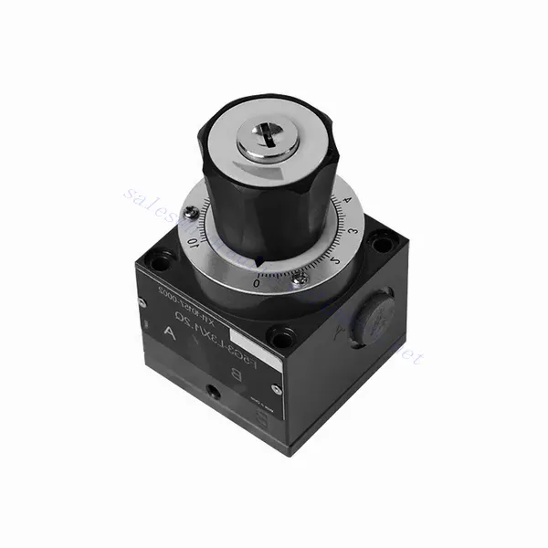
Katup Hidrolik Throttle Halus Seri F
Sebagai salah satu produsen, pemasok, dan eksportir silinder hidrolik, Kami menawarkan silinder hidrolik dan banyak produk lainnya.
Silakan hubungi kami untuk informasi lebih lanjut.
Surat:sales@hydraulic-cylinders.net
Produsen pemasok eksportir silinder hidrolik.
Katup Hidrolik Throttle Halus Seri F
The F series fine throttle hydraulic valve is an exceptional component designed to deliver precise control and enhanced efficiency in hydraulic systems. With its advanced fine throttle functionality, this valve offers unparalleled flow regulation, allowing operators to achieve optimal performance and control over hydraulic actuators.
The F series fine throttle hydraulic valve is an indispensable component for achieving precision and control in hydraulic systems. With its advanced fine throttle functionality, this valve allows for precise flow regulation, enhancing performance and efficiency. By following the recommended usage methods and maintenance guidelines, operators can ensure the longevity, reliability, and optimal functionality of the F series fine throttle hydraulic valve. Upgrade your hydraulic system with this exceptional valve and experience enhanced precision, control, and productivity.
F Series Fine Throttle Hydraulic Valve Key Characteristics:
- Fine Throttle Control:
- The F series valve is equipped with a delicate throttle mechanism that enables precise adjustment of the flow rate of hydraulic fluid.
- Operators can finely tune the flow control, facilitating accurate speed and position control of hydraulic actuators.
- Peningkatan Kinerja:
- This hydraulic valve exhibits exceptional performance thanks to its precise flow regulation capabilities.
- By ensuring optimal flow rates, the F series valve minimizes energy loss, reduces system inefficiencies, and maximizes overall performance.
- Aplikasi Serbaguna:
- The f series fine throttle hydraulic valve suits various hydraulic systems and applications.
- It can seamlessly integrate into various industries, including manufacturing, agriculture, construction, and more.
- Daya Tahan dan Keandalan:
- Built with high-quality materials and robust construction, this valve is designed to withstand demanding operating conditions.
- Its durability ensures long-term reliability, minimizing downtime and maintenance costs.
F Series Fine Throttle Hydraulic Valve Parameter:
| Posisi pemasangan | Opsional | ||
| Berat | –Manifold mounting | kg | 1 |
| – Threaded connection | kg | 1.6 | |
| – Sub-plate mounting | kg | 1.8 | |
| Cairan | Mineral oil suitable for NBR and FKM seal | ||
| Ester fosfat untuk segel FKM | |||
| Tingkat kontaminasi | Tingkat kontaminasi cairan maksimum yang diizinkan: Kelas 9. NAS 1638 atau 20/18/15, ISO4406 | ||
| Kisaran suhu fluida | ℃ | -30 hingga +80 (segel NBR) | |
| -20 hingga +80 (segel FKM) | |||
| Kisaran viskositas | mm2/S | 2.8 to 380 | |
| Tekanan operasi maks. | batang | 210 | |
| Laju aliran maks. | L/menit | 80 | |
| Adjustment angle | ° | 300 | |
| Operating torque | at 100bar | Nm | 1.1 |
| at 200bar | Nm | 1.8 | |
F Series Fine Throttle Hydraulic Valve Advantages:
• Digunakan untuk pemasangan sub-pelat bawah
• Used in screw connection
• Digunakan dalam pemasangan blok jalur oli
• With lockable knob with scale
Usage Method Of F Series Fine Throttle Hydraulic Valve:
- Evaluasi Sistem:
- Begin by thoroughly assessing the hydraulic system, considering flow requirements, pressure differentials, and actuator specifications.
- Determine if fine throttle control is necessary to achieve the desired precision and control.
- Pemilihan Katup:
- Select the appropriate variant of the F series valve based on system parameters and specific flow control requirements.
- Consider aspects such as maximum flow rate, pressure rating, and compatibility with other system components.
- Instalasi:
- Follow the manufacturer’s installation instructions carefully, ensuring accurate alignment and secure valve connections.
- Pay close attention to flow direction indicators, ensuring proper installation of fittings and seals.
- Fine Throttle Adjustment:
- Once installed, adjust the fine throttle control of the valve to achieve the desired flow rate.
- Operators can fine-tune the flow control to match the specific requirements of the hydraulic actuators, optimizing performance and precision.
How Hydraulic Solenoid Valve Works?
A hydraulic solenoid valve is an electromechanical device that controls the flow of hydraulic fluid in a system. It operates using the principle of an energized solenoid, which creates a magnetic field to actuate the valve mechanism. Here’s a breakdown of how a hydraulic solenoid valve works:
- Struktur Katup:
- A hydraulic solenoid valve typically consists of a valve body, a solenoid coil, a plunger or spool mechanism, and various ports for fluid flow.
- The valve body houses the internal components and fluid passages necessary for controlling the flow.
- The solenoid coil surrounds the plunger or spool and generates a magnetic field when energized.
- Normally Closed (NC) and Normally Open (NO) States:
- Hydraulic solenoid valves can be configured as normally closed (NC) or normally open (NO) based on their resting state.
- In the NC configuration, the valve is closed when de-energized, blocking the fluid flow.
- In the NO configuration, the valve is open when de-energized, allowing fluid flow.
- Pengoperasian Katup:
- When an electrical current is applied to the solenoid coil, it generates a magnetic field.
- This magnetic field attracts the plunger or spool, causing it to move against a spring or pressure differential, depending on the valve design.
- The movement of the plunger or spool opens or closes the valve ports, controlling the flow of hydraulic fluid.
- Kontrol Listrik:
- The solenoid coil of a hydraulic solenoid valve is typically controlled by an electrical circuit, such as a switch or a programmable logic controller (PLC).
- When the circuit is energized, it allows current to flow through the solenoid coil, activating the valve.
- When the circuit is de-energized, the magnetic field dissipates, and the valve returns to its resting state.
- Flow Direction and Pressure:
- Hydraulic solenoid valves have different port configurations to control the direction and pressure of fluid flow.
- Depending on the valve design, there may be inlet ports, outlet ports, and exhaust ports.
- The position of the plunger or spool determines which ports are connected, allowing fluid to flow in specific directions and controlling pressure levels.
- Aplikasi:
- Hydraulic solenoid valves are widely used in various industries and applications where precise control of fluid flow is required.
- They can be found in hydraulic systems for industrial machinery, construction equipment, agricultural machinery, and automotive applications.
- Benefits:
- Hydraulic solenoid valves offer several advantages, including fast response times, precise control, compact size, and ease of integration into hydraulic systems.
- Their electrical control allows for automation and remote operation, enhancing system efficiency and convenience.
Kemampuan & Kapasitas Pabrik:
(1) Perakitan
Kami memiliki platform perakitan penelitian dan pengembangan independen kelas satu. Bengkel produksi silinder hidrolik memiliki empat jalur perakitan silinder pengangkat semi-otomatis dan satu jalur perakitan silinder kemiringan otomatis, dengan kapasitas produksi tahunan yang dirancang sebesar 1 juta keping. Bengkel silinder khusus dilengkapi dengan berbagai spesifikasi sistem perakitan pembersihan semi-otomatis dengan kapasitas produksi tahunan yang dirancang sebesar 200.000 dan dilengkapi dengan peralatan permesinan CNC yang terkenal, pusat permesinan, peralatan khusus pemrosesan silinder presisi tinggi, mesin las robot, mesin pembersih otomatis, mesin perakitan silinder otomatis, dan jalur produksi pengecatan otomatis. Peralatan penting yang ada lebih dari 300 set (set). Alokasi optimal dan penggunaan sumber daya peralatan yang efisien memastikan persyaratan akurasi produk dan memenuhi kebutuhan produk berkualitas tinggi.


(2) Pemesinan
Bengkel permesinan dilengkapi dengan pusat pembubutan rel miring yang disesuaikan, pusat permesinan, mesin pengasah berkecepatan tinggi, robot pengelasan, dan peralatan terkait lainnya, yang dapat menangani pemrosesan tabung silinder dengan diameter bagian dalam maksimum 400mm dan panjang maksimum 6 meter.

(3) Pengelasan

(4) Pengecatan & pelapisan
Dengan jalur pelapisan cat berbasis air otomatis silinder kecil dan menengah, untuk mencapai bongkar muat robot otomatis dan penyemprotan otomatis, kapasitas desain 4000 buah per shift;
Kami juga memiliki lini produksi cat semi-otomatis untuk silinder besar yang ditenagai oleh rantai daya, dengan kapasitas desain 60 kasus per shift.


(5) Pengujian
Kami memiliki fasilitas inspeksi kelas satu dan test bed untuk memastikan bahwa kinerja silinder memenuhi persyaratan.

Kami adalah salah satu produsen silinder hidrolik terbaik. Kami dapat menawarkan silinder hidrolik yang lengkap. Kami juga menyediakan produk yang sesuai. gearbox pertanian. Kami telah mengekspor produk kami ke klien di seluruh dunia dan mendapatkan reputasi yang baik karena kualitas produk dan layanan purna jual kami yang unggul. Kami menyambut pelanggan di dalam dan luar negeri untuk menghubungi kami untuk menegosiasikan bisnis, bertukar informasi, dan bekerja sama dengan kami!
Aplikasi Silinder Hidraulik:
