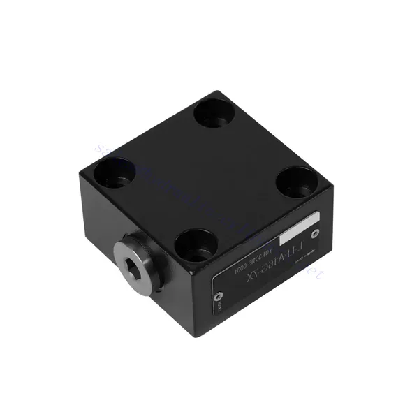
L-LFA Series Directional Control Hydraulic Valve
Sebagai salah satu produsen, pemasok, dan eksportir silinder hidrolik, Kami menawarkan silinder hidrolik dan banyak produk lainnya.
Silakan hubungi kami untuk informasi lebih lanjut.
Surat:sales@hydraulic-cylinders.net
Produsen pemasok eksportir silinder hidrolik.
L-LFA Series Directional Control Hydraulic Valve
The L-LFA series directional control hydraulic valve is a cutting-edge component designed to deliver precise control and optimal performance in hydraulic systems. With its advanced features and robust construction, this valve provides reliable and efficient directional control for various applications.
The L-LFA series directional control hydraulic valve is a game-changer for hydraulic systems, offering precise directional control, versatility, and durability. By following the recommended usage methods and maintenance guidelines, you can harness the full potential of the L-LFA series valve and experience enhanced control, efficiency, and productivity in your hydraulic applications. Upgrade your hydraulic system today and unlock the advantages of precision and efficiency with the L-LFA series directional control hydraulic valve.
L-LFA Series Directional Control Hydraulic Valve Key Characteristics:
- Accurate Directional Control:
- The L-LFA series valve offers exceptional directional control, allowing precise and efficient management of fluid flow in hydraulic systems.
- This characteristic enables operators to direct hydraulic fluid to specific actuators or hydraulic components, facilitating smooth and controlled movement.
- Versatile Configuration Options:
- This valve is available in various configurations, including 2-way, 3-way, and 4-way options, ensuring compatibility with diverse hydraulic system requirements.
- The 2-way configuration facilitates simple on/off control, while the 3-way and 4-way configurations enable more complex functions such as cylinder extension, retraction, and bi-directional control.
- High-Performance Construction:
- The L-LFA series valve is engineered with high-quality materials and precision manufacturing techniques to ensure durability and longevity.
- Its robust construction allows it to withstand high pressures, temperature variations, and harsh operating conditions, ensuring reliable performance even in demanding environments.
- Waktu Respon Cepat:
- This valve boasts an impressive response time, enabling rapid and efficient fluid flow control within the hydraulic system.
- The quick response time facilitates precise and immediate adjustments, resulting in enhanced system performance and reduced energy consumption.
L-LFA Series Directional Control Hydraulic Valve Parameter:
| Maximum working pressure | Without directional valve | batang | 420 | |||||
| – Oil port A、B、X、Z1、Z2 | batang | 315; 350; 420(Depends on top-mounted directional valve) | ||||||
| – Oil port Y | batang | Equivalent to the return pressure of a top-mounted directional valve | ||||||
| Cairan | Oli mineral cocok untuk seal NBR dan FKM | |||||||
| Ester fosfat untuk segel FKM | ||||||||
| Kisaran suhu fluida | ℃ | -30 hingga +80 (segel NBR) | ||||||
| -20 hingga +80 (segel FKM) | ||||||||
| Kisaran viskositas | mm2/S | 2.8 to 380 | ||||||
| Tingkat kontaminasi | Tingkat kontaminasi cairan maksimum yang diperbolehkan: Kelas 9. NAS 1638 atau 20/18/15, ISO4406 | |||||||
L-LFA Series Directional Control Hydraulic Valve Advantages:
• Basic type D with remote control
• With stroke limiter H
• Built-in shuttle valve G
• Built-in directional seat valve R, RF
• Can be equipped with directional valve WE
Usage Method Of L-LFA Series Directional Control Hydraulic Valve:
- Evaluasi Sistem:
- Evaluate your hydraulic system and identify the specific directional control requirements.
- Determine whether the L-LFA series valve suits your system based on flow rates, pressure ratings, and compatibility with your application.
- Pemilihan Katup:
- Select the appropriate variant of the L-LFA series valve based on your system parameters and directional control needs.
- Consider factors such as valve type (2-way, 3-way, or 4-way), flow capacity, pressure rating, and compatibility with your specific application.
- Instalasi:
- Ikuti petunjuk pemasangan dari pabrikan dengan cermat untuk memastikan penyelarasan yang tepat dan pemasangan katup yang aman.
- Use compatible hydraulic fittings, adapters, and seals to establish leak-free connections. Tighten the connections adequately, avoiding overtightening that could damage the valve or fittings.
- Integrasi Sistem:
- Connect the hydraulic lines to the appropriate ports of the L-LFA series valve, ensuring the correct flow direction.
- Verify that the valve is installed in the correct orientation, as indicated by the directional arrows on the valve body.
- Operasi dan Kontrol:
- Familiarize yourself with the control mechanisms of the L-LFA Series Valve, such as levers, knobs, or solenoids.
- Ensure that the valve is actuated correctly and that the desired hydraulic flow is achieved based on the system requirements.
Bagaimana Cara Memasang Katup Pelepas Tekanan Hidrolik?
Memasang katup pelepas tekanan hidrolik merupakan langkah penting untuk memastikan keamanan dan fungsi yang tepat dari sistem hidrolik. Berikut panduan langkah demi langkah tentang cara memasang katup pelepas tekanan hidrolik:
- Identifikasi Katupnya: Tentukan jenis dan model spesifik katup pelepas tekanan hidrolik yang Anda gunakan. Pastikan katup tersebut sesuai untuk aplikasi Anda dan kompatibel dengan persyaratan sistem hidrolik Anda.
- Siapkan Alat dan Bahan yang Dibutuhkan: Siapkan alat dan bahan yang diperlukan, termasuk fitting hidrolik yang sesuai, adaptor, kunci pas, pita Teflon (perekat ulir), dan pengukur tekanan jika diperlukan. Lihat petunjuk pabrikan untuk alat atau komponen spesifik yang dibutuhkan.
- Siapkan Sistem Hidrolik: Matikan sistem hidrolik dan kurangi tekanan dengan mengaktifkan katup pelepas atau menarik silinder hidrolik. Langkah ini penting untuk keselamatan dan mencegah pergerakan yang tidak disengaja atau kebocoran cairan hidrolik.
- Identifikasi Titik Pelepas Tekanan: Tentukan lokasi optimal untuk memasang katup pelepas tekanan hidrolik dalam sistem hidrolik Anda. Katup tersebut harus diposisikan di hilir pompa sebelum komponen sensitif apa pun untuk melindunginya dari tekanan berlebih. Konsultasikan skema sistem hidrolik atau mintalah saran profesional jika perlu.
- Pasang Katup: Pasang katup pelepas tekanan hidrolik dengan aman di lokasi yang dipilih menggunakan braket atau klem yang sesuai. Pastikan katup diposisikan dengan benar, sejajarkan port masuk dan keluar dengan arah aliran. Ikuti petunjuk pabrikan untuk persyaratan pemasangan khusus.
- Hubungkan Port Masuk dan Keluar: Pasang selang atau pipa hidrolik ke port masuk dan keluar katup pelepas tekanan. Gunakan fitting dan adaptor hidrolik yang sesuai untuk membuat sambungan yang kedap udara. Oleskan pita Teflon atau sealant ulir pada ulir jantan fitting untuk memastikan sambungan yang aman dan kedap. Kencangkan sambungan menggunakan kunci inggris untuk menghindari kebocoran, tetapi berhati-hatilah agar tidak terlalu kencang.
- Atur Pengaturan Pelepasan Tekanan: Sebagian besar katup pelepas tekanan hidrolik dilengkapi dengan pengaturan pelepas tekanan yang dapat disesuaikan. Sesuaikan katup pelepas ke titik pelepas tekanan yang diinginkan menggunakan panduan pabrikan. Beberapa katup mungkin memerlukan pengukur tekanan untuk mengatur tekanan pelepas secara akurat. Pasang pengukur tekanan sementara, jika diperlukan, dan sesuaikan katup pelepas hingga tekanan yang diinginkan tercapai.
- Uji Sistem: Setelah katup pelepas tekanan hidrolik terpasang, kembalikan tekanan sistem hidrolik secara perlahan. Pantau pengukur tekanan atau amati perilaku sistem untuk memastikan bahwa katup pelepas berfungsi dengan benar. Katup pelepas harus terbuka dan mengalihkan tekanan berlebih ketika mencapai titik yang telah ditentukan, sehingga mencegah kerusakan pada sistem.
- Memantau dan Memelihara: Periksa katup pelepas tekanan hidrolik secara berkala untuk mendeteksi tanda-tanda kebocoran, kerusakan, atau penurunan kinerja. Bersihkan katup dan area sekitarnya untuk menghilangkan kotoran dan serpihan yang dapat memengaruhi pengoperasiannya. Ikuti jadwal dan panduan perawatan yang direkomendasikan pabrikan untuk memastikan kinerja optimal dan umur pakai yang panjang.
Kemampuan & Kapasitas Pabrik:
(1) Perakitan
Kami memiliki platform perakitan penelitian dan pengembangan independen kelas satu. Bengkel produksi silinder hidrolik memiliki empat jalur perakitan silinder pengangkat semi-otomatis dan satu jalur perakitan silinder kemiringan otomatis, dengan kapasitas produksi tahunan yang dirancang sebesar 1 juta keping. Bengkel silinder khusus dilengkapi dengan berbagai spesifikasi sistem perakitan pembersihan semi-otomatis dengan kapasitas produksi tahunan yang dirancang sebesar 200.000 dan dilengkapi dengan peralatan permesinan CNC yang terkenal, pusat permesinan, peralatan khusus pemrosesan silinder presisi tinggi, mesin las robot, mesin pembersih otomatis, mesin perakitan silinder otomatis, dan jalur produksi pengecatan otomatis. Peralatan penting yang ada lebih dari 300 set (set). Alokasi optimal dan penggunaan sumber daya peralatan yang efisien memastikan persyaratan akurasi produk dan memenuhi kebutuhan produk berkualitas tinggi.


(2) Pemesinan
Bengkel permesinan dilengkapi dengan pusat pembubutan rel miring yang disesuaikan, pusat permesinan, mesin pengasah berkecepatan tinggi, robot pengelasan, dan peralatan terkait lainnya, yang dapat menangani pemrosesan tabung silinder dengan diameter bagian dalam maksimum 400mm dan panjang maksimum 6 meter.

(3) Pengelasan

(4) Pengecatan & pelapisan
Dengan jalur pelapisan cat berbasis air otomatis silinder kecil dan menengah, untuk mencapai bongkar muat robot otomatis dan penyemprotan otomatis, kapasitas desain 4000 buah per shift;
Kami juga memiliki lini produksi cat semi-otomatis untuk silinder besar yang ditenagai oleh rantai daya, dengan kapasitas desain 60 kasus per shift.


(5) Pengujian
Kami memiliki fasilitas inspeksi kelas satu dan test bed untuk memastikan bahwa kinerja silinder memenuhi persyaratan.

Kami adalah salah satu produsen silinder hidrolik terbaik. Kami dapat menawarkan silinder hidrolik yang lengkap. Kami juga menyediakan produk yang sesuai. gearbox pertanian. Kami telah mengekspor produk kami ke klien di seluruh dunia dan mendapatkan reputasi yang baik karena kualitas produk dan layanan purna jual kami yang unggul. Kami menyambut pelanggan di dalam dan luar negeri untuk menghubungi kami untuk menegosiasikan bisnis, bertukar informasi, dan bekerja sama dengan kami!
Aplikasi Silinder Hidraulik:
