

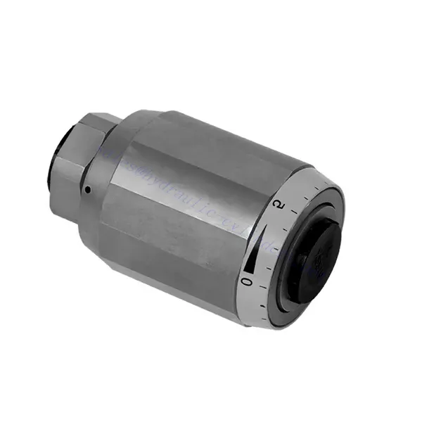
Katup Hidrolik Throttle dan Katup Pemeriksa Throttle Seri MG/MK
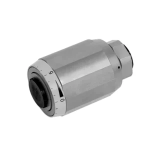

Katup hidrolik pengatur aliran dan katup periksa aliran seri MG/MK adalah komponen hidrolik serbaguna dan berkinerja tinggi yang dirancang untuk mengoptimalkan kontrol dan efisiensi dalam sistem hidrolik. Dengan fungsi pengatur aliran dan katup periksa aliran yang unik, katup ini menawarkan kontrol aliran yang presisi dan memastikan pengoperasian aktuator hidrolik yang lancar.
Katup hidrolik pengatur dan pengecekan aliran seri MG/MK adalah solusi serbaguna dan andal untuk kontrol aliran yang presisi dan peningkatan efisiensi sistem. Dengan fungsi pengatur aliran, fitur pengecekan aliran, dan opsi kontrol aliran yang dapat disesuaikan, katup ini memberikan kinerja luar biasa dalam berbagai aplikasi hidrolik. Dengan mengikuti metode penggunaan dan panduan perawatan yang direkomendasikan, operator dapat memastikan umur panjang, keandalan, dan fungsi optimal dari katup hidrolik pengatur dan pengecekan aliran seri MG/MK. Tingkatkan sistem hidrolik Anda dengan katup canggih ini dan rasakan peningkatan kontrol, efisiensi, dan produktivitas.
Karakteristik Utama Katup Hidrolik Throttle dan Throttle Check Seri MG/MK:
- Fungsionalitas Throttle:
- Katup seri MG/MK memiliki fungsi pengatur aliran yang mengatur laju aliran fluida hidrolik.
- Hal ini memungkinkan kontrol yang tepat terhadap aliran fluida, sehingga memungkinkan penyesuaian kecepatan dan responsivitas aktuator secara halus.
- Fungsi Pemeriksaan Throttle:
- Selain pengendalian katup gas, katup ini juga dilengkapi fungsi pemeriksaan katup gas.
- Fitur pemeriksaan katup pengatur memungkinkan katup berfungsi sebagai katup searah, mencegah aliran balik dan menjaga stabilitas sistem.
- Fleksibilitas Kontrol Aliran:
- Katup Seri MG/MK menawarkan berbagai pilihan kontrol aliran, memungkinkan penyesuaian untuk memenuhi persyaratan aplikasi tertentu.
- Perangkat ini dapat dikonfigurasi untuk berbagai laju aliran, perbedaan tekanan, dan ukuran aktuator, sehingga memastikan kompatibilitas dengan beragam sistem hidrolik.
- Peningkatan Efisiensi Sistem:
- Dengan menyediakan kontrol aliran yang tepat, katup meminimalkan kehilangan energi dan mengoptimalkan efisiensi sistem secara keseluruhan.
- Hal ini memungkinkan operator untuk menyesuaikan aliran hidrolik dengan kebutuhan beban tertentu, sehingga mengurangi konsumsi daya yang tidak perlu.
- Kinerja yang Andal:
- Katup Seri MG/MK dirancang untuk tahan terhadap kondisi operasi yang berat dan memberikan kinerja yang konsisten.
- Konstruksi yang kokoh dan material berkualitas tinggi menjamin daya tahan dan keandalan dalam berbagai aplikasi.
Parameter Katup Hidrolik Throttle dan Throttle Check Seri MG/MK:
| Ukuran | 6 | 8 | 10 | 15 | 20 | 25 | 30 | |
| Berat | kg | 0.3 | 0.4 | 0.7 | 1.3 | 2.2 | 3.6 | 4.5 |
| Tekanan operasi maks. | batang | 315 bar | ||||||
| Tekanan retak untuk tipe MK | batang | 0.5 | ||||||
| Laju aliran maks. | L/menit | 400 | ||||||
| Kisaran viskositas | mm2/S | 10 hingga 800 | ||||||
| Kisaran suhu fluida | ℃ | -30℃ hingga +80℃ | ||||||
| Cairan | Minyak mineral; Ester fosfat | |||||||
| Tingkat kontaminasi | Tingkat kontaminasi cairan maksimum yang diizinkan: Kelas 9. NAS 1638 atau 20/18/15, ISO4406 | |||||||
Keunggulan Katup Hidrolik Throttle dan Throttle Check Seri MG/MK:
• Digunakan dalam instalasi pipa langsung
• Berkaitan dengan tekanan dan viskositas
Metode Penggunaan Katup Hidrolik Throttle dan Throttle Check Seri MG/MK:
- Evaluasi Sistem:
- Assess the hydraulic system’s requirements, including flow rates, pressure differentials, and actuator specifications.
- Identifikasi kebutuhan akan fungsi throttle dan pengecekan throttle dalam sistem.
- Pemilihan Katup:
- Pilih varian katup seri MG/MK yang sesuai berdasarkan parameter sistem dan karakteristik kontrol aliran yang diinginkan.
- Pertimbangkan faktor-faktor seperti laju aliran maksimum, peringkat tekanan, dan kompatibilitas dengan komponen sistem lainnya.
- Instalasi:
- Follow the manufacturer’s installation instructions and ensure proper alignment and connection of the valve.
- Perhatikan panah arah aliran dan pastikan sambungan dan segel terpasang dengan aman.
- Penyesuaian Aliran:
- Sesuaikan pengaturan katup untuk mencapai laju aliran yang diinginkan.
- Lakukan penyesuaian halus pada kontrol throttle untuk mengoptimalkan kinerja aktuator dan efisiensi sistem.
Bagaimana Cara Kerja Katup Kontrol Hidraulik?
Katup kontrol hidrolik adalah komponen penting dalam sistem hidrolik yang mengatur aliran dan tekanan fluida hidrolik. Katup ini berfungsi sebagai mekanisme kontrol untuk mengarahkan fluida ke berbagai aktuator hidrolik dan mengendalikan kecepatan serta arah pergerakannya. Cara kerja katup kontrol hidrolik dapat dijelaskan sebagai berikut:
- Struktur Katup:
- Katup kontrol hidrolik terdiri dari badan katup yang menampung berbagai komponen internal, seperti kumparan, katup penutup, atau cakram.
- Badan katup berisi port, saluran, dan ruang yang memperlancar aliran fluida hidrolik.
- Posisi Katup:
- Katup kontrol hidrolik biasanya memiliki beberapa posisi, termasuk terbuka, tertutup, dan terbuka sebagian.
- Dalam posisi tertutup, katup menghalangi aliran fluida sepenuhnya.
- Dalam posisi terbuka, katup memungkinkan cairan mengalir bebas melalui lubang-lubang tertentu.
- Pada posisi terbuka sebagian, katup membatasi atau mengontrol laju aliran fluida.
- Pengoperasian Katup Spool:
- Katup spool umumnya digunakan dalam sistem kontrol hidrolik. Katup ini terdiri dari spool silindris dengan alur atau saluran.
- Kumparan tersebut terletak di dalam badan katup dan dapat digerakkan secara memanjang.
- Dengan menggeser kumparan, bagian-bagian yang berbeda akan sejajar dengan port tertentu, sehingga memungkinkan atau menghalangi aliran fluida ke aktuator yang berbeda.
- Pergerakan kumparan biasanya dicapai dengan menggunakan sambungan mekanis, solenoida, atau tekanan hidrolik yang bekerja pada kumparan.
- Pengoperasian Katup Poppet:
- Katup poppet adalah jenis katup kontrol hidrolik lainnya. Katup ini menggunakan poppet atau cakram yang dapat bergerak untuk mengontrol aliran fluida.
- Saat poppet berada pada posisi tertutup, poppet tersebut bersandar pada dudukan, sehingga aliran fluida terhambat.
- Untuk membuka katup, poppet digerakkan menjauh dari dudukannya, sehingga cairan dapat mengalir melalui saluran.
- Pergerakan katup dapat dicapai melalui sambungan mekanis atau tekanan hidrolik.
- Mekanisme Kontrol:
- Katup kontrol hidrolik dapat dioperasikan secara manual, mekanis, atau melalui cara elektrik.
- Kontrol manual melibatkan penggunaan tuas, kenop, atau pegangan untuk memposisikan elemen katup.
- Kontrol mekanis memanfaatkan hubungan mekanis atau aktuator untuk menggerakkan elemen katup.
- Kontrol kelistrikan menggunakan solenoid atau perangkat lain yang dikontrol secara elektrik untuk menggeser elemen katup.
- Kontrol Aktuator:
- Katup kontrol hidrolik mengarahkan fluida ke berbagai aktuator hidrolik, seperti silinder atau motor.
- Dengan mengendalikan posisi katup, sistem hidrolik dapat mengatur kecepatan, arah, dan gaya aktuator.
- Sebagai contoh, menyesuaikan posisi katup dapat mengontrol pemanjangan atau penarikan silinder hidrolik.
- Stabilitas dan Keamanan Sistem:
- Katup kontrol hidrolik memainkan peran penting dalam menjaga stabilitas dan keamanan sistem.
- Katup pelepas tekanan sering kali diintegrasikan ke dalam sistem kontrol hidrolik untuk melindungi dari tekanan berlebih.
- Katup pelepas tekanan ini mengalihkan cairan berlebih ke saluran keluar bertekanan rendah, sehingga mencegah kerusakan pada sistem.
Kemampuan & Kapasitas Pabrik:
(1) Perakitan
Kami memiliki platform perakitan penelitian dan pengembangan independen kelas satu. Bengkel produksi silinder hidrolik memiliki empat jalur perakitan silinder pengangkat semi-otomatis dan satu jalur perakitan silinder kemiringan otomatis, dengan kapasitas produksi tahunan yang dirancang sebesar 1 juta keping. Bengkel silinder khusus dilengkapi dengan berbagai spesifikasi sistem perakitan pembersihan semi-otomatis dengan kapasitas produksi tahunan yang dirancang sebesar 200.000 dan dilengkapi dengan peralatan permesinan CNC yang terkenal, pusat permesinan, peralatan khusus pemrosesan silinder presisi tinggi, mesin las robot, mesin pembersih otomatis, mesin perakitan silinder otomatis, dan jalur produksi pengecatan otomatis. Peralatan penting yang ada lebih dari 300 set (set). Alokasi optimal dan penggunaan sumber daya peralatan yang efisien memastikan persyaratan akurasi produk dan memenuhi kebutuhan produk berkualitas tinggi.


(2) Pemesinan
Bengkel permesinan dilengkapi dengan pusat pembubutan rel miring yang disesuaikan, pusat permesinan, mesin pengasah berkecepatan tinggi, robot pengelasan, dan peralatan terkait lainnya, yang dapat menangani pemrosesan tabung silinder dengan diameter bagian dalam maksimum 400mm dan panjang maksimum 6 meter.


(3) Pengelasan


(4) Pengecatan & pelapisan
Dengan jalur pelapisan cat berbasis air otomatis silinder kecil dan menengah, untuk mencapai bongkar muat robot otomatis dan penyemprotan otomatis, kapasitas desain 4000 buah per shift;
Kami juga memiliki lini produksi cat semi-otomatis untuk silinder besar yang ditenagai oleh rantai daya, dengan kapasitas desain 60 kasus per shift.


(5) Pengujian
Kami memiliki fasilitas inspeksi kelas satu dan test bed untuk memastikan bahwa kinerja silinder memenuhi persyaratan.


Kami adalah salah satu produsen silinder hidrolik terbaik. Kami dapat menawarkan silinder hidrolik yang lengkap. Kami juga menyediakan produk yang sesuai. gearbox pertanian. Kami telah mengekspor produk kami ke klien di seluruh dunia dan mendapatkan reputasi yang baik karena kualitas produk dan layanan purna jual kami yang unggul. Kami menyambut pelanggan di dalam dan luar negeri untuk menghubungi kami untuk menegosiasikan bisnis, bertukar informasi, dan bekerja sama dengan kami!