
WMM Series Directional Hydraulic Valve With Mechanical, Manual Operation
Sebagai salah satu produsen, pemasok, dan eksportir silinder hidrolik, Kami menawarkan silinder hidrolik dan banyak produk lainnya.
Silakan hubungi kami untuk informasi lebih lanjut.
Surat:sales@hydraulic-cylinders.net
Produsen pemasok eksportir silinder hidrolik.
WMM Series Directional Hydraulic Valve With Mechanical, Manual Operation
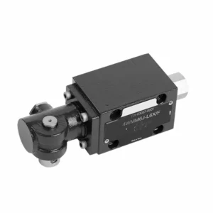
The WMM series directional hydraulic valve with mechanical, manual operation is a versatile and reliable solution designed to control hydraulic systems precisely. This hydraulic valve offers enhanced efficiency and flexibility with its advanced features and robust construction.
The WMM series directional hydraulic valve with mechanical, manual operation is a reliable and versatile solution for hydraulic systems. Its automatic manual operation and precise directional control offer enhanced flexibility and control for various applications. Following the recommended usage methods and adhering to regular maintenance practices, the WMM series hydraulic valve will continue providing efficient and reliable operation. Upgrade your hydraulic system with the WMM series directional valve and experience the benefits of enhanced control and versatility.
WMM Series Directional Hydraulic Valve With Mechanical, Manual Operation Key Characteristics:
- Operasi Mekanik, Manual:
- The WMM series hydraulic valve features a mechanical, manual operation, allowing operators to control the valve position manually.
- Hal ini memberikan fleksibilitas dan kontrol dalam aplikasi yang menginginkan atau memerlukan pengoperasian manual.
- Kontrol Arah:
- Katup hidrolik ini memungkinkan kontrol aliran fluida terarah yang tepat dalam sistem hidrolik.
- Hal ini memungkinkan operator untuk memilih jalur aliran yang diinginkan, memastikan operasi yang efisien dan andal.
- Konstruksi Tahan Lama:
- The WMM series hydraulic valve is constructed with high-quality materials, ensuring durability and longevity.
- Desainnya yang kokoh dapat menahan kondisi pengoperasian yang berat, memberikan kinerja yang andal.
- Ukuran Kompak:
- The valve’s compact size allows easy integration into hydraulic systems with limited space.
- It is ideal for applications where space is a constraint without compromising performance.
WMM Series Directional Hydraulic Valve With Mechanical, Manual Operation Parameter:
NG6
| Kisaran suhu fluida | ℃ | -30 hingga +80 (segel NBR) | |
| -20 hingga +80 (segel FKM) | |||
| Tekanan operasi maks. Port | Pelabuhan ABP | batang | 315 |
| Pelabuhan T | batang | 160 | |
| Laju aliran maks. | L/menit | 60 | |
| Area aliran (mengalihkan posisi netral) | Tipe Q | mm2 | Untuk simbol Q, 6% dari penampang nominal |
| Tipe W | mm2 | Untuk simbol W, 3% dari penampang nominal | |
| Cairan | Minyak mineral; Ester fosfat | ||
| Kisaran viskositas | mm2/S | 2,8 hingga 500 | |
| Tingkat kontaminasi | Tingkat kontaminasi cairan maksimum yang diizinkan: Kelas 9. NAS 1638 atau 20/18/15, ISO4406 | ||
| Berat | kg | 1.6 | |
NG10
| Kisaran suhu fluida | ℃ | -30 hingga +80 (segel NBR) | |
| -20 hingga +80 (segel FKM) | |||
| Tekanan operasi maks. Port | Pelabuhan ABP | batang | 315 |
| Pelabuhan T | batang | 160 | |
| Laju aliran maks. | L/menit | 120 | |
| Penampang aliran (pengalihan posisi netral) | Tipe V | mm2 | 11(A/B → T);10.3(P → A/B) |
| Tipe W | mm2 | 2,5(A/B → T) | |
| Tipe Q | mm2 | 5.5(A/B → T) | |
| Cairan | Minyak mineral; Ester fosfat | ||
| Kisaran viskositas | mm2/S | 2,8 hingga 500 | |
| Tingkat kontaminasi | Tingkat kontaminasi cairan maksimum yang diizinkan: Kelas 9. NAS 1638 atau 20/18/15, ISO4406 | ||
| Berat | kg | 4.4 | |
NG16-32
| NS | 16 | 25 | 32 |
| Berat | about 8 | about 12.2 | about 49 |
| Actuation force with detent N | about 75 | about 105 | about 170 |
| with spring return N | |||
| Actuation angle about the neutral position | 2*26° | 2*32° | 2*30° |
| Max. operating pressure Port A,B,P bar | 315 | ||
| Port T bar | 250 | ||
| Cairan | Oli mineral cocok untuk seal NBR dan FKM | ||
| Phosphate ester – for FKM seal | |||
| Kisaran suhu fluida | -30 to +80(NBR seal) | ||
| -20 hingga +80 (segel FKM) | |||
| Viscosity range mm2/S | 2.8 to 380 | ||
| Tingkat kontaminasi | Tingkat kontaminasi cairan maksimum yang diizinkan: Kelas 9. NAS 1638 atau 20/18/15, ISO4406 | ||
WMM Series Directional Hydraulic Valve With Mechanical, Manual Operation Advantages:
• Katup geser arah kerja langsung katup geser arah kerja langsung
• Sub-plate mounting
• Handle control
• Installation face follow DIN 24340 A, ISO 4401
Usage Method Of WMM Series Directional Hydraulic Valve With Mechanical, Manual Operation:
- Integrasi Sistem:
- Identify the appropriate location for the WMM series hydraulic valve within the hydraulic system, considering the desired flow direction and control requirements.
- Pastikan kompatibilitas dengan spesifikasi tekanan dan aliran sistem.
- Pasang katup dengan aman menggunakan braket atau aksesori pemasangan yang sesuai.
- Koneksi Fluida:
- Pilih sambungan dan selang hidrolik yang kompatibel untuk sambungan yang aman dan bebas kebocoran.
- Ikuti petunjuk pabrik untuk nilai torsi yang tepat selama proses pemasangan.
- Gunakan perekat ulir atau selotip yang sesuai untuk memastikan segel yang andal.
- Operasi Manual:
- Familiarize yourself with the manual operation mechanism of the valve, including the lever or knob used to control the hydraulic valve position.
- Pastikan operator memahami prosedur yang benar untuk menyesuaikan posisi katup secara manual.
- Kalibrasi Sistem:
- Calibrate the hydraulic valve position and movement according to the desired flow direction and control requirements.
- Sesuaikan katup secara manual untuk mencapai jalur aliran yang diinginkan dan memastikan fungsionalitas yang tepat.
How To Adjust Valves On A Hydraulic Roller Cam?
Adjusting valves on a hydraulic roller cam requires careful attention to detail and following the proper procedure. Here’s a step-by-step guide to help you adjust the valves correctly:
- Siapkan Mesin:
- Ensure the engine is turned off and cool to the touch before starting the adjustment process.
- Locate the valve covers and remove them to access the valve train components.
- Identifikasi Urutan Penyetelan Katup yang Benar:
- Konsultasikan spesifikasi pabrikan mesin atau buku petunjuk servis untuk menentukan urutan penyetelan katup yang tepat untuk mesin spesifik Anda.
- Temukan Posisi Titik Mati Atas (TDC):
- Rotate the engine’s crankshaft in the normal direction of rotation until the number one piston reaches the top dead center position on its compression stroke.
- Use a timing mark on the harmonic balancer or flywheel and a timing pointer to identify the TDC position accurately.
- Adjusting Valve Lash:
- Begin with the first cylinder in the valve adjustment sequence.
- Loosen the lock nut on the rocker arm stud using an appropriate wrench or socket.
- Use a feeler gauge of the recommended thickness specified by the engine manufacturer to check the valve lash (clearance) between the rocker arm and the valve stem.
- Slide the feeler gauge between the rocker arm and the valve stem. You should feel slight resistance but still be able to move the gauge back and forth.
- Adjust the valve lash by either tightening or loosening the rocker arm stud until the proper clearance is achieved. Turning the stud clockwise decreases the clearance, while counterclockwise increases it.
- Once you’ve set the correct valve lash, hold the rocker arm stud in place and tighten the lock nut securely.
- Ulangi Prosesnya:
- Move to the next cylinder in the valve adjustment sequence and repeat steps 4 and 5 until all the valves have been adjusted.
- Pasang kembali penutup katup:
- Setelah Anda menyelesaikan penyetelan katup pada semua silinder, pasang kembali penutup katup dan pastikan tertutup rapat untuk mencegah kebocoran oli.
- Periksa Ulang:
- After adjusting the valves, it’s a good practice to go through the entire valve adjustment sequence once more to confirm that all clearances are within the specified range.
Kemampuan & Kapasitas Pabrik:
(1) Perakitan
Kami memiliki platform perakitan penelitian dan pengembangan independen kelas satu. Bengkel produksi silinder hidrolik memiliki empat jalur perakitan silinder pengangkat semi-otomatis dan satu jalur perakitan silinder kemiringan otomatis, dengan kapasitas produksi tahunan yang dirancang sebesar 1 juta keping. Bengkel silinder khusus dilengkapi dengan berbagai spesifikasi sistem perakitan pembersihan semi-otomatis dengan kapasitas produksi tahunan yang dirancang sebesar 200.000 dan dilengkapi dengan peralatan permesinan CNC yang terkenal, pusat permesinan, peralatan khusus pemrosesan silinder presisi tinggi, mesin las robot, mesin pembersih otomatis, mesin perakitan silinder otomatis, dan jalur produksi pengecatan otomatis. Peralatan penting yang ada lebih dari 300 set (set). Alokasi optimal dan penggunaan sumber daya peralatan yang efisien memastikan persyaratan akurasi produk dan memenuhi kebutuhan produk berkualitas tinggi.


(2) Pemesinan
Bengkel permesinan dilengkapi dengan pusat pembubutan rel miring yang disesuaikan, pusat permesinan, mesin pengasah berkecepatan tinggi, robot pengelasan, dan peralatan terkait lainnya, yang dapat menangani pemrosesan tabung silinder dengan diameter bagian dalam maksimum 400mm dan panjang maksimum 6 meter.

(3) Pengelasan

(4) Pengecatan & pelapisan
Dengan jalur pelapisan cat berbasis air otomatis silinder kecil dan menengah, untuk mencapai bongkar muat robot otomatis dan penyemprotan otomatis, kapasitas desain 4000 buah per shift;
Kami juga memiliki lini produksi cat semi-otomatis untuk silinder besar yang ditenagai oleh rantai daya, dengan kapasitas desain 60 kasus per shift.


(5) Pengujian
Kami memiliki fasilitas inspeksi kelas satu dan test bed untuk memastikan bahwa kinerja silinder memenuhi persyaratan.

Kami adalah salah satu produsen silinder hidrolik terbaik. Kami dapat menawarkan silinder hidrolik yang lengkap. Kami juga menyediakan produk yang sesuai. gearbox pertanian. Kami telah mengekspor produk kami ke klien di seluruh dunia dan mendapatkan reputasi yang baik karena kualitas produk dan layanan purna jual kami yang unggul. Kami menyambut pelanggan di dalam dan luar negeri untuk menghubungi kami untuk menegosiasikan bisnis, bertukar informasi, dan bekerja sama dengan kami!
Aplikasi Silinder Hidraulik:
