
Katup Hidrolik Arah Seri WMR Dengan Operasi Mekanis dan Manual
Sebagai salah satu produsen, pemasok, dan eksportir silinder hidrolik, Kami menawarkan silinder hidrolik dan banyak produk lainnya.
Silakan hubungi kami untuk informasi lebih lanjut.
Surat:sales@hydraulic-cylinders.net
Produsen pemasok eksportir silinder hidrolik.
Katup Hidrolik Arah Seri WMR Dengan Operasi Mekanis dan Manual
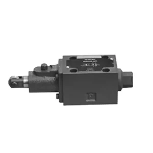
Katup hidrolik terarah seri WMR dengan pengoperasian manual mekanis merupakan solusi mutakhir yang dirancang untuk memberikan kontrol presisi dalam sistem hidrolik. Katup ini menawarkan efisiensi dan fleksibilitas yang lebih baik berkat fitur-fitur canggih dan konstruksinya yang kokoh.
Katup hidrolik terarah seri WMR dengan pengoperasian mekanis dan manual merupakan solusi yang andal dan serbaguna untuk sistem hidrolik. Pengoperasian otomatis dan manualnya serta kontrol arahnya yang presisi menawarkan fleksibilitas dan kendali yang lebih baik untuk berbagai aplikasi. Dengan mengikuti metode penggunaan yang disarankan dan praktik perawatan rutin, katup seri WMR akan terus memberikan pengoperasian yang efisien dan andal. Tingkatkan sistem hidrolik Anda dengan katup hidrolik terarah seri WMR dan rasakan manfaat kendali dan fleksibilitas yang ditingkatkan.
Katup Hidrolik Arah Seri WMR Dengan Pengoperasian Mekanik dan Manual Karakteristik Utama:
- Operasi Mekanik, Manual:
- Katup seri WMR dilengkapi dengan pengoperasian mekanis manual, yang memungkinkan operator mengendalikan posisi katup secara manual.
- Hal ini memberikan fleksibilitas dan kontrol dalam aplikasi yang menginginkan atau memerlukan pengoperasian manual.
- Kontrol Arah:
- Katup hidrolik ini memungkinkan kontrol aliran fluida terarah yang tepat dalam sistem hidrolik.
- Hal ini memungkinkan operator untuk memilih jalur aliran yang diinginkan, memastikan operasi yang efisien dan andal.
- Konstruksi Tahan Lama:
- Katup seri WMR dibuat dengan bahan berkualitas tinggi, menjamin daya tahan dan umur panjang.
- Desainnya yang kokoh dapat menahan kondisi pengoperasian yang berat, memberikan kinerja yang andal.
- Berbagai Macam Aplikasi:
- Katup seri WMR cocok untuk berbagai industri dan aplikasi, termasuk manufaktur, konstruksi, pertanian, dll.
- Ini dapat digunakan dalam sistem hidrolik yang memerlukan kontrol fluida yang akurat dan efisien.
Katup Hidrolik Arah Seri WMR Dengan Operasi Mekanik, Manual Parameter:
NG6
| Posisi pemasangan | Opsional | ||
| Kisaran suhu fluida | ℃ | -30 hingga +80 (segel NBR) | |
| -20 hingga +80 (segel FKM) | |||
| Tekanan operasi maks. Port | Pelabuhan ABP | batang | 315 |
| Pelabuhan T | batang | 60 | |
| Laju aliran maks. | L/menit | 60 | |
| Penampang aliran (pengalihan posisi netral) | Tipe Q | mm2 | Untuk simbol Q, 6% dari penampang nominal |
| Tipe W | mm2 | Untuk simbol W, 3% dari penampang nominal | |
| Cairan | Minyak mineral; Ester fosfat | ||
| Kisaran viskositas | mm2/S | 2,8 hingga 500 | |
| Tingkat kontaminasi | Tingkat kontaminasi cairan maksimum yang diizinkan: Kelas 9. NAS 1638 atau 20/18/15, ISO4406 | ||
| Berat | kg | 1.4 | |
NG10
| Posisi pemasangan | Opsional | ||
| Kisaran suhu fluida | ℃ | -30 hingga +80 (segel NBR) | |
| -20 hingga +80 (segel FKM) | |||
| Tekanan operasi maks. Port | Pelabuhan ABP | batang | 315 |
| Pelabuhan T | batang | 60 | |
| Laju aliran maks. | L/menit | 120 | |
| Penampang aliran (pengalihan posisi netral) | Tipe V | mm2 | 11(A/B → T);10.3(P → A/B) |
| Tipe W | mm2 | 2,5(A/B → T) | |
| Tipe Q | mm2 | 5.5(A/B → T) | |
| Cairan | Minyak mineral; Ester fosfat | ||
| Kisaran viskositas | mm2/S | 2,8 hingga 500 | |
| Tingkat kontaminasi | Tingkat kontaminasi cairan maksimum yang diizinkan: Kelas 9. NAS 1638 atau 20/18/15, ISO4406 | ||
| Berat | kg | 4 | |
Katup Hidrolik Arah Seri WMR Dengan Pengoperasian Mekanik dan Manual Keunggulan:
• Katup geser arah kerja langsung katup geser arah kerja langsung
• Roda gulir dapat berputar 90°
• Sembilan belas fungsi katup geser standar
Metode Penggunaan Katup Hidrolik Arah Seri WMR Dengan Operasi Mekanis dan Manual:
- Integrasi Sistem:
- Identifikasi lokasi yang tepat untuk katup seri WMR dalam sistem hidrolik, dengan mempertimbangkan arah aliran yang diinginkan dan persyaratan kontrol.
- Pastikan kompatibilitas dengan spesifikasi tekanan dan aliran sistem.
- Pasang katup dengan aman menggunakan braket atau aksesori pemasangan yang sesuai.
- Koneksi Fluida:
- Pilih sambungan dan selang hidrolik yang kompatibel untuk sambungan yang aman dan bebas kebocoran.
- Ikuti petunjuk pabrik untuk nilai torsi yang tepat selama proses pemasangan.
- Gunakan perekat ulir atau selotip yang sesuai untuk memastikan segel yang andal.
- Operasi Manual:
- Biasakan diri Anda dengan mekanisme operasi manual katup, termasuk tuas atau kenop yang digunakan untuk mengontrol posisi katup.
- Pastikan operator memahami prosedur yang benar untuk menyesuaikan posisi katup secara manual.
- Kalibrasi Sistem:
- Kalibrasi posisi dan pergerakan katup sesuai dengan arah aliran yang diinginkan dan persyaratan kontrol.
- Sesuaikan katup secara manual untuk mencapai jalur aliran yang diinginkan dan memastikan fungsionalitas yang tepat.
Bagaimana Cara Menyesuaikan Pengangkat Katup Hidrolik?
Penyetelan pengangkat katup hidrolik merupakan tugas perawatan yang krusial untuk memastikan performa mesin yang optimal dan mencegah masalah seperti kebisingan rangkaian katup dan penurunan daya. Berikut panduan langkah demi langkah tentang cara menyetel pengangkat katup hidrolik:
- Siapkan Mesin:
- Sebelum memulai proses penyesuaian, pastikan mesin dimatikan dan dingin saat disentuh.
- Lepaskan semua komponen yang diperlukan untuk mengakses penutup katup, seperti rakitan pembersih udara atau kabel busi.
- Identifikasi Urutan Penyetelan Katup yang Benar:
- Konsultasikan spesifikasi pabrikan mesin atau buku petunjuk servis untuk menentukan urutan penyetelan katup yang tepat untuk mesin spesifik Anda.
- Beberapa mesin memiliki urutan penyalaan yang menentukan laju pembakaran, sedangkan mesin lainnya memiliki instruksi khusus berdasarkan penomoran silinder.
- Temukan Posisi Titik Mati Atas (TDC):
- Putar poros engkol mesin ke arah putaran normal hingga piston nomor satu mencapai posisi titik mati atas (TDC) pada langkah kompresinya.
- Gunakan tanda waktu pada penyeimbang harmonik atau roda gila dan penunjuk waktu untuk menentukan posisi TDC secara akurat.
- Menyetel Pengangkat Katup:
- Mulailah dengan silinder pertama dalam urutan penyesuaian katup.
- Lepaskan penutup katup untuk mengakses lengan ayun dan pengangkat katup.
- Kendurkan mur pengunci pada lengan ayun menggunakan kunci pas atau soket yang sesuai.
- Putar sekrup penyetel atau kancing pada lengan ayun searah jarum jam untuk memperkecil celah katup, atau berlawanan arah jarum jam untuk menambahnya.
- Periksa spesifikasi pabrikan mesin untuk mengetahui celah katup yang direkomendasikan. Gunakan feeler gauge untuk mengukur celah antara lengan ayun dan batang katup.
- Sesuaikan pengangkat katup hingga mencapai jarak bebas yang tepat. Anda akan merasakan sedikit hambatan, tetapi masih dapat menggerakkan feeler gauge maju mundur.
- Tahan sekrup penyetel atau kancing pada tempatnya dan kencangkan mur pengunci dengan kuat.
- Ulangi Prosesnya:
- Pindah ke silinder berikutnya dalam urutan penyesuaian katup dan ulangi langkah 4 dan 5 hingga semua pengangkat katup telah disesuaikan.
- Pasang kembali penutup katup:
- Setelah Anda menyelesaikan penyetelan katup pada semua silinder, pasang kembali penutup katup dan pastikan tertutup rapat untuk mencegah kebocoran oli.
- Periksa Ulang:
- Setelah menyetel pengangkat katup, sebaiknya ulangi seluruh rangkaian penyetelan katup untuk memastikan semua kelonggaran berada dalam rentang yang ditentukan.
Kemampuan & Kapasitas Pabrik:
(1) Perakitan
Kami memiliki platform perakitan penelitian dan pengembangan independen kelas satu. Bengkel produksi silinder hidrolik memiliki empat jalur perakitan silinder pengangkat semi-otomatis dan satu jalur perakitan silinder kemiringan otomatis, dengan kapasitas produksi tahunan yang dirancang sebesar 1 juta keping. Bengkel silinder khusus dilengkapi dengan berbagai spesifikasi sistem perakitan pembersihan semi-otomatis dengan kapasitas produksi tahunan yang dirancang sebesar 200.000 dan dilengkapi dengan peralatan permesinan CNC yang terkenal, pusat permesinan, peralatan khusus pemrosesan silinder presisi tinggi, mesin las robot, mesin pembersih otomatis, mesin perakitan silinder otomatis, dan jalur produksi pengecatan otomatis. Peralatan penting yang ada lebih dari 300 set (set). Alokasi optimal dan penggunaan sumber daya peralatan yang efisien memastikan persyaratan akurasi produk dan memenuhi kebutuhan produk berkualitas tinggi.


(2) Pemesinan
Bengkel permesinan dilengkapi dengan pusat pembubutan rel miring yang disesuaikan, pusat permesinan, mesin pengasah berkecepatan tinggi, robot pengelasan, dan peralatan terkait lainnya, yang dapat menangani pemrosesan tabung silinder dengan diameter bagian dalam maksimum 400mm dan panjang maksimum 6 meter.

(3) Pengelasan

(4) Pengecatan & pelapisan
Dengan jalur pelapisan cat berbasis air otomatis silinder kecil dan menengah, untuk mencapai bongkar muat robot otomatis dan penyemprotan otomatis, kapasitas desain 4000 buah per shift;
Kami juga memiliki lini produksi cat semi-otomatis untuk silinder besar yang ditenagai oleh rantai daya, dengan kapasitas desain 60 kasus per shift.


(5) Pengujian
Kami memiliki fasilitas inspeksi kelas satu dan test bed untuk memastikan bahwa kinerja silinder memenuhi persyaratan.

Kami adalah salah satu produsen silinder hidrolik terbaik. Kami dapat menawarkan silinder hidrolik yang lengkap. Kami juga menyediakan produk yang sesuai. gearbox pertanian. Kami telah mengekspor produk kami ke klien di seluruh dunia dan mendapatkan reputasi yang baik karena kualitas produk dan layanan purna jual kami yang unggul. Kami menyambut pelanggan di dalam dan luar negeri untuk menghubungi kami untuk menegosiasikan bisnis, bertukar informasi, dan bekerja sama dengan kami!
Aplikasi Silinder Hidraulik:
