

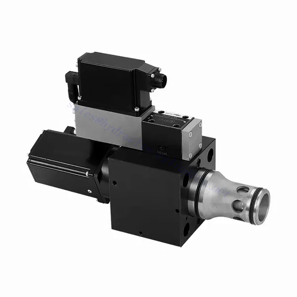
Katup Hidrolik Aliran Respons Tinggi Seri WRCE 2 dan 3 arah
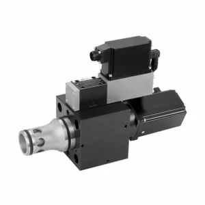

Katup hidrolik aliran respons tinggi 2 dan 3 arah seri WRCE merupakan komponen hidrolik luar biasa yang dirancang untuk memberikan kinerja luar biasa dalam aplikasi kontrol fluida. Dengan kemampuan aliran respons tinggi, katup ini merevolusi sistem hidrolik dengan menyediakan kontrol aliran yang presisi dan efisien.
Katup hidrolik aliran respons tinggi 2 dan 3 arah seri WRCE menetapkan standar baru dalam presisi dan efisiensi kontrol aliran. Dengan kemampuan aliran respons tinggi, desain ringkas, dan fleksibilitasnya, katup ini memberdayakan sistem hidrolik untuk mencapai kinerja dan efisiensi energi yang optimal. Dengan mengikuti metode penggunaan dan panduan perawatan yang disarankan, Anda dapat memanfaatkan potensi penuh katup seri WRCE dan merasakan peningkatan kontrol serta produktivitas dalam aplikasi hidrolik Anda. Tingkatkan sistem hidrolik Anda hari ini dan dapatkan keunggulan efisiensi dan presisi dengan katup hidrolik aliran respons tinggi 2 dan 3 arah seri WRCE.
Karakteristik Utama Katup Hidrolik Aliran Respons Tinggi 2 dan 3 Arah Seri WRCE:
- Aliran Respons Tinggi:
- Katup seri WRCE dirancang untuk menawarkan kontrol aliran respons tinggi, memastikan penyesuaian yang cepat dan akurat pada laju aliran fluida.
- Karakteristik ini memungkinkan kontrol yang tepat atas aktuator hidrolik, sehingga menghasilkan peningkatan kinerja sistem, pengurangan konsumsi energi, dan peningkatan efisiensi keseluruhan.
- Konfigurasi 2 dan 3 Arah yang Serbaguna:
- Katup ini tersedia dalam konfigurasi 2 arah dan 3 arah, memberikan fleksibilitas untuk memenuhi berbagai persyaratan sistem hidrolik.
- Konfigurasi 2 arah memungkinkan kontrol hidup/mati yang sederhana, sementara desain 3 arah memungkinkan kontrol arah, sehingga ideal untuk aplikasi seperti perpanjangan dan penarikan aktuator.
- Desain Kompak:
- Katup seri WRCE memiliki desain yang ringkas, sehingga cocok untuk instalasi di tempat yang ruangnya terbatas.
- Ukuran yang ringkas ini memungkinkan integrasi yang mudah ke dalam berbagai sistem hidrolik tanpa mengurangi kinerja atau fungsionalitas.
- Peringkat Tekanan Tinggi:
- Katup ini dibuat untuk menahan lingkungan bertekanan tinggi, memastikan pengoperasian yang andal bahkan dalam aplikasi hidrolik yang menantang.
- Konstruksinya yang kokoh dan peringkat tekanan tinggi membuatnya cocok untuk digunakan dalam sistem yang memerlukan kontrol aliran efisien dalam kondisi operasi ekstrem.
Parameter Katup Hidrolik Aliran Respons Tinggi 2 dan 3 Arah Seri WRCE:
| Umum | |||||
| NS NG | 32 | 40 | 50 | ||
| Berat | kg | 11.2 | 17.3 | 24.6 | |
| Weight with shut-off valve …../…WK or …/…WL… | kg | 12.5 | 18.6 | 25.9 | |
| Ukuran katup kontrol pilot (pilot) | NG | 6 | 6 | 6 | |
| Posisi pemasangan | Apa saja, sebaiknya horizontal | ||||
| Kisaran suhu penyimpanan | ℃ | –20 hingga +80 | |||
| Kisaran suhu keadaan | ℃ | –20 hingga +50 | |||
| Hidrolik (diukur dengan HLP32, ϑoil=40℃ ±5℃) | |||||
| Tekanan operasi maks. | – Panggung utama Pelabuhan A dan B | batang | NS 32~40: 350, NS 50: 420 | ||
| – Port katup kontrol pilot X | 315 | ||||
| – Port katup kontrol pilot Y | 210 | ||||
| Aliran terukur Δp=5bar | – Specifications …S…L (linear) | L/menit | 800 | 1200 | 2000 |
| – Specifications …S…R (linear with progressive fine control range) | 600 | 850 | 1400 | ||
| Aliran nominal katup pilot pada Δp=70bar | L/menit | 12 | 40 | 40 | |
| Kebocoran katup pilot pada P=100bar | L/menit | 0.3 | 0.7 | 0.7 | |
| Cairan hidrolik | Minyak mineral (HL,HLP) sesuai DIN 51524 | ||||
| Kisaran suhu fluida hidrolik | ℃ | 20 hingga +80; lebih disukai +40 hingga +50 | |||
| Kisaran viskositas | mm2/S | 20 hingga 380; lebih disukai 30 hingga 45 | |||
| Tingkat kontaminasi maksimum yang diizinkan dari cairan hidrolik, kelas kebersihan menurut ISO 4406 (c) | Kelas 20/18/15 | ||||
| Histeresis | % | ≤ 0,2 | |||
| Histeresis | % | ≤ 0,1 | |||
| Sensitivitas respons | % | ≤ 0,1 | |||
| Waktu Respons (tanda langkah 0 ~ 100%) | MS | ≤ 20 | |||
| Data listrik | |||||
| Jenis tegangan | Tegangan searah | ||||
| Jenis sinyal | Analog | ||||
| Kalibrasi titik pembukaan | % | ≦ 1 | |||
| Nol shift saat terjadi perubahan: | – Suhu fluida hidrolik | %/10K | ≦ 0,3 | ≦ 0,3 | ≦ 0,3 |
| – Tekanan pilot di X | %/100bar | ≦ 0,7 | ≦ 0,7 | ≦ 0,7 | |
| – Tekanan aliran balik di Y | %/batang | ≦ 0,3 | ≦ 0,3 | ≦ 0,3 | |
| Kelas perlindungan katup menurut EN60529 | IP65 dengan konektor pasangan terpasang dan terkunci | ||||
Keunggulan Katup Hidrolik Aliran Respons Tinggi 2 dan 3 Arah Seri WRCE:
• Katup throttle respons frekuensi tinggi kartrid dua tahap yang dioperasikan pilot
• Cocok untuk kontrol loop tertutup posisi, tekanan, gaya dan kecepatan
• Katup kontrol pilot: katup proporsional respons frekuensi tinggi kerja langsung enam port dengan umpan balik listrik
• Panggung utama: kontrol posisi loop tertutup
• Elektronik kontrol loop terbuka dan loop tertutup (OBE) terintegrasi
Metode Penggunaan Katup Hidrolik Aliran Respons Tinggi Seri WRCE 2 dan 3 Arah :
- Penilaian Sistem:
- Evaluasi sistem hidrolik Anda dan tentukan persyaratan kontrol aliran spesifik.
- Identifikasi apakah katup seri WRCE kompatibel dengan sistem Anda berdasarkan faktor-faktor seperti laju aliran, peringkat tekanan, dan fungsi kontrol yang diinginkan.
- Pemilihan Katup:
- Pilih varian katup seri WRCE yang tepat berdasarkan parameter sistem dan kebutuhan kontrol aliran Anda.
- Pertimbangkan faktor-faktor seperti kapasitas aliran, peringkat tekanan, waktu respons, dan kompatibilitas dengan aplikasi spesifik Anda.
- Instalasi:
- Follow the manufacturer’s installation instructions carefully to ensure proper alignment and secure mounting of the valve.
- Pastikan sambungan bebas kebocoran dengan menggunakan fitting hidrolik, adaptor, dan seal yang sesuai. Kencangkan sambungan dengan benar untuk mencegah kebocoran cairan.
- Integrasi Sinyal Kontrol:
- Hubungkan saluran sinyal kontrol katup ke perangkat kontrol yang sesuai, seperti modul kontrol hidrolik, unit kontrol elektronik, atau tuas kontrol manual.
- Pastikan pemasangan kabel dan kompatibilitas yang tepat antara katup dan perangkat kontrol untuk mencapai kontrol aliran yang akurat dan responsif.
Bagaimana Cara Menghubungkan Katup Kontrol Hidrolik?
Untuk memasang katup kontrol hidrolik, ikuti langkah-langkah berikut:
- Identifikasi Jenis Katup: Tentukan jenis katup kontrol hidrolik yang Anda gunakan, seperti katup kontrol arah, katup kontrol tekanan, atau katup kontrol aliran. Pastikan katup tersebut sesuai dengan aplikasi Anda dan kompatibel dengan sistem hidrolik Anda.
- Kumpulkan Alat dan Bahan yang Diperlukan: Collect the necessary tools and materials, including appropriate hydraulic fittings, adapters, hoses, and wrenches. Refer to the manufacturer’s instructions for any specific tools or components needed.
- Siapkan Sistem Hidrolik: Matikan sistem hidrolik dan kurangi tekanan dengan mengaktifkan katup pelepas atau menarik silinder hidrolik. Langkah ini penting untuk keselamatan dan mencegah pergerakan yang tidak disengaja atau kebocoran cairan hidrolik.
- Identifikasi Arah Aliran: Tentukan arah aliran dalam sistem hidrolik Anda. Biasanya, arah aliran ditunjukkan oleh tanda panah pada komponen hidrolik. Pastikan Anda memahami arah aliran yang benar sebelum melanjutkan.
- Temukan Titik Instalasi: Tentukan lokasi optimal untuk memasang katup kontrol hidrolik di sistem hidrolik Anda. Pertimbangkan faktor-faktor seperti aksesibilitas, kedekatan dengan aktuator atau komponen hidrolik, dan kemudahan pengoperasian. Pastikan tersedia cukup ruang agar katup dapat terpasang dengan aman.
- Pasang Katup: Securely mount the hydraulic control valve in the chosen location using appropriate brackets or clamps. Ensure the valve is positioned correctly, aligning the inlet and outlet ports with the flow direction. Follow the manufacturer’s instructions for the specific mounting requirements of your valve.
- Hubungkan Port Masuk dan Keluar: Pasang selang atau pipa hidrolik ke port masuk dan keluar katup kontrol hidrolik. Gunakan fitting dan adaptor hidrolik yang sesuai untuk memastikan sambungan bebas kebocoran. Kencangkan sambungan menggunakan kunci inggris untuk memastikan pemasangan yang aman, tetapi hindari mengencangkannya terlalu kencang.
- Hubungkan Jalur Kontrol: If your hydraulic control valve requires external control signals, connect the control lines from the control device, such as a joystick, lever, or solenoid, to the appropriate ports on the valve. Follow the manufacturer’s instructions for the correct wiring or connection configuration.
- Uji Sistem: Setelah katup kontrol hidrolik terpasang, kembalikan tekanan sistem hidrolik secara perlahan. Uji sistem untuk memastikan katup berfungsi dengan benar. Operasikan perangkat kontrol dan amati respons komponen hidrolik untuk memastikan katup mengendalikan aliran, tekanan, atau arah sesuai keinginan.
- Penyetelan halus dan penyesuaian: Make any necessary adjustments to the hydraulic control valve to achieve the desired flow, pressure, or direction control. Refer to the manufacturer’s instructions for specific adjustment procedures. Regularly monitor the system for any leaks, pressure inconsistencies, or abnormal behavior.
Kemampuan & Kapasitas Pabrik:
(1) Perakitan
Kami memiliki platform perakitan penelitian dan pengembangan independen kelas satu. Bengkel produksi silinder hidrolik memiliki empat jalur perakitan silinder pengangkat semi-otomatis dan satu jalur perakitan silinder kemiringan otomatis, dengan kapasitas produksi tahunan yang dirancang sebesar 1 juta keping. Bengkel silinder khusus dilengkapi dengan berbagai spesifikasi sistem perakitan pembersihan semi-otomatis dengan kapasitas produksi tahunan yang dirancang sebesar 200.000 dan dilengkapi dengan peralatan permesinan CNC yang terkenal, pusat permesinan, peralatan khusus pemrosesan silinder presisi tinggi, mesin las robot, mesin pembersih otomatis, mesin perakitan silinder otomatis, dan jalur produksi pengecatan otomatis. Peralatan penting yang ada lebih dari 300 set (set). Alokasi optimal dan penggunaan sumber daya peralatan yang efisien memastikan persyaratan akurasi produk dan memenuhi kebutuhan produk berkualitas tinggi.


(2) Pemesinan
Bengkel permesinan dilengkapi dengan pusat pembubutan rel miring yang disesuaikan, pusat permesinan, mesin pengasah berkecepatan tinggi, robot pengelasan, dan peralatan terkait lainnya, yang dapat menangani pemrosesan tabung silinder dengan diameter bagian dalam maksimum 400mm dan panjang maksimum 6 meter.


(3) Pengelasan


(4) Pengecatan & pelapisan
Dengan jalur pelapisan cat berbasis air otomatis silinder kecil dan menengah, untuk mencapai bongkar muat robot otomatis dan penyemprotan otomatis, kapasitas desain 4000 buah per shift;
Kami juga memiliki lini produksi cat semi-otomatis untuk silinder besar yang ditenagai oleh rantai daya, dengan kapasitas desain 60 kasus per shift.


(5) Pengujian
Kami memiliki fasilitas inspeksi kelas satu dan test bed untuk memastikan bahwa kinerja silinder memenuhi persyaratan.


Kami adalah salah satu produsen silinder hidrolik terbaik. Kami dapat menawarkan silinder hidrolik yang lengkap. Kami juga menyediakan produk yang sesuai. gearbox pertanian. Kami telah mengekspor produk kami ke klien di seluruh dunia dan mendapatkan reputasi yang baik karena kualitas produk dan layanan purna jual kami yang unggul. Kami menyambut pelanggan di dalam dan luar negeri untuk menghubungi kami untuk menegosiasikan bisnis, bertukar informasi, dan bekerja sama dengan kami!