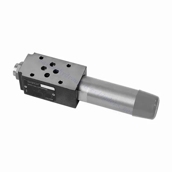
Katup Hidrolik Pengurang Tekanan yang Dioperasikan Langsung Seri ZDR
Sebagai salah satu produsen, pemasok, dan eksportir silinder hidrolik, Kami menawarkan silinder hidrolik dan banyak produk lainnya.
Silakan hubungi kami untuk informasi lebih lanjut.
Surat:sales@hydraulic-cylinders.net
Produsen pemasok eksportir silinder hidrolik.
Katup Hidrolik Pengurang Tekanan yang Dioperasikan Langsung Seri ZDR
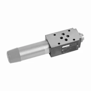
Katup hidrolik pengurang tekanan yang dioperasikan langsung seri ZDR adalah komponen yang sangat efisien dan andal yang memberikan kontrol tekanan akurat dalam sistem hidrolik. Dengan desain yang dioperasikan langsung dan kinerja yang luar biasa, katup ini memastikan pengurangan tekanan yang tepat untuk memenuhi persyaratan sistem tertentu.
Katup hidrolik pengurang tekanan yang dioperasikan langsung seri ZDR adalah solusi berkinerja tinggi untuk kontrol tekanan yang presisi dalam sistem hidrolik. Dengan desain yang dioperasikan langsung, kontrol tekanan yang akurat, rentang tekanan yang luas, dan kapasitas aliran yang tinggi, katup ini memastikan pengurangan tekanan yang efisien dan andal sekaligus melindungi komponen sistem. Dengan mengikuti metode penggunaan dan praktik perawatan yang direkomendasikan, katup seri ZDR memberikan kinerja yang andal, memperpanjang umur sistem hidrolik. Tingkatkan sistem hidrolik Anda dengan katup hidrolik pengurang tekanan yang dioperasikan langsung seri ZDR dan rasakan kontrol tekanan optimal untuk meningkatkan efisiensi dan produktivitas sistem.
Karakteristik Utama Katup Hidrolik Pengurang Tekanan yang Dioperasikan Langsung Seri ZDR:
- Desain Operasi Langsung:
- Katup seri ZDR memiliki desain pengoperasian langsung, yang memungkinkannya untuk memberikan kontrol tekanan yang presisi tanpa memerlukan sirkuit pilot eksternal.
- Desain ini menyederhanakan pemasangan dan mengurangi kompleksitas pada sistem hidrolik.
- Kontrol Tekanan Akurat:
- Katup ini menawarkan akurasi luar biasa dalam pengendalian tekanan, memungkinkan sistem hidrolik untuk mempertahankan rentang tekanan yang diinginkan dengan keandalan tinggi.
- Hal ini memastikan pengoperasian yang stabil dan melindungi komponen sistem yang sensitif dari tekanan berlebihan.
- Rentang Tekanan Lebar:
- Katup seri ZDR tersedia dalam berbagai rentang tekanan, sehingga cocok untuk beragam aplikasi hidrolik.
- Fleksibilitas dalam rentang tekanan memungkinkan penyesuaian untuk mencocokkan persyaratan sistem tertentu dan mengoptimalkan kinerja.
- Kapasitas Aliran Tinggi:
- Katup ini memiliki kapasitas aliran yang sangat baik, sehingga mampu menangani laju aliran tinggi sekaligus mempertahankan kontrol tekanan yang presisi.
- Memastikan pengaturan cairan yang efisien dan pengoperasian sistem tanpa gangguan, bahkan dalam aplikasi yang menuntut.
Parameter Katup Hidrolik Pengurang Tekanan yang Dioperasikan Langsung Seri ZDR:
| Spesifikasi | NG10 | NG16 | ||
| Cairan | Oli mineral cocok untuk seal NBR dan FKM | |||
| Ester fosfat untuk segel FKM | ||||
| Kisaran suhu fluida | ℃ | -30 hingga +80 (segel NBR) | ||
| -20 hingga +80 (segel FKM) | ||||
| Kisaran viskositas | mm2/S | 10 hingga 800 | ||
| Tingkat kontaminasi | Tingkat kontaminasi cairan maksimum yang diizinkan: Kelas 9. NAS 1638 atau 20/18/15, ISO4406 | |||
| Tekanan nominal | batang | 315 | ||
| Tekanan operasi maks. | Pelabuhan P | batang | 315 | |
| Tekanan operasi maks. | Pelabuhan A | batang | 315 | 250 |
| Tekanan operasi maks. | Pelabuhan Y | batang | Terpisah dan pada tekanan nol ke tangki | |
| Pengaturan tekanan | Menit. | batang | Tergantung pada aliran (lihat kurva) | |
| Maks. | batang | 50; 100; 200; 315 | 50; 100; 200; 250 | |
| Laju aliran maks. | L/menit | 120 | 220 | |
| Berat | kg | sekitar 6,5 | sekitar 8,8 | |
Keunggulan Katup Hidrolik Pengurang Tekanan yang Dioperasikan Langsung Seri ZDR:
• Struktur tipe sandwich
• Permukaan pemasangan mengikuti standar DIN 24340 A dan ISO 4401
• Empat rentang tekanan
• Dua jenis penyesuaian: kenop, sekrup penyesuaian dengan tutup pelindung
• Dengan antarmuka pengukur tekanan
• Katup satu arah opsional
Metode Penggunaan Katup Hidrolik Pengurang Tekanan yang Dioperasikan Langsung Seri ZDR:
- Analisis Sistem:
- Lakukan analisis sistem hidrolik secara menyeluruh untuk menentukan persyaratan pengendalian tekanan spesifik.
- Pertimbangkan tekanan operasi maksimum, rentang tekanan yang diinginkan, dan laju aliran.
- Pemilihan Katup:
- Pilih varian katup seri ZDR yang sesuai berdasarkan spesifikasi kontrol tekanan sistem.
- Pertimbangkan peringkat tekanan, kapasitas aliran, dan kompatibilitas dengan komponen sistem lainnya.
- Instalasi:
- Ikuti petunjuk pabrikan untuk memasang katup pengurang tekanan yang dioperasikan langsung seri ZDR dengan benar pada sistem hidrolik.
- Pastikan penyelarasan yang tepat dan sambungan yang aman untuk mencegah kebocoran dan mengoptimalkan kinerja.
- Kalibrasi:
- Kalibrasi katup untuk mengatur tekanan hilir yang diinginkan.
- Gunakan pengukur tekanan atau perangkat pengukuran lainnya untuk menyesuaikan katup agar kontrol tekanan optimal dan akurat.
Bagaimana Cara Kerja Katup Pemilih Hidraulik?
Katup pemilih hidrolik, juga dikenal sebagai katup pengalih hidrolik atau katup kontrol hidrolik, adalah perangkat yang digunakan untuk mengarahkan aliran fluida hidrolik dalam sistem hidrolik. Perangkat ini memungkinkan operator untuk mengontrol jalur aliran fluida dengan memilih sirkuit atau komponen hidrolik yang berbeda untuk dioperasikan. Berikut adalah uraian cara kerja katup pemilih hidrolik:
- Konstruksi Katup:
- Katup pemilih hidrolik terdiri dari badan dengan banyak port dan saluran internal.
- Biasanya, alat ini memiliki mekanisme penggerak, seperti tuas atau solenoida, untuk mengontrol pergerakan katup atau poppet.
- Konfigurasi Port:
- Katup pemilih memiliki beberapa port, biasanya diberi label A, B, dan C, atau terkadang disebut sebagai P, T, dan A/B/C.
- Port P (Tekanan) terhubung ke pompa hidrolik atau sisi tekanan tinggi dari sistem.
- Port T (Tangki) terhubung ke reservoir hidrolik atau sisi tekanan rendah dari sistem.
- Port A, B, dan C adalah port keluaran yang terhubung ke berbagai sirkuit atau komponen hidrolik.
- Posisi Katup:
- Katup pemilih memiliki posisi berbeda yang menentukan jalur aliran fluida hidrolik.
- Posisi umum meliputi “A,” “B,” “C,” “AB,” “AC,” dan “BC,” tergantung pada desain katup tertentu.
- Kontrol Aliran Fluida:
- Ketika katup berada pada posisi netral atau standar, yang biasanya diberi label "N," aliran fluida terblokir, dan tidak ada aliran yang terjadi antara port mana pun.
- Ketika operator mengaktifkan katup dengan menggerakkan tuas atau memberi energi pada solenoida, spul atau poppet katup bergeser ke posisi yang berbeda, memungkinkan aliran fluida.
- Pemilihan Jalur Aliran:
- Dengan menggerakkan mekanisme penggerak, operator dapat memilih jalur aliran yang diinginkan.
- Sebagai contoh, ketika katup berada pada posisi “A,” cairan mengalir dari port P ke port A, sehingga memungkinkan sirkuit hidrolik atau komponen yang terhubung ke port A untuk beroperasi.
- Beberapa Jalur Aliran:
- Tergantung pada desain katup tertentu, katup pemilih hidrolik dapat menyediakan beberapa jalur aliran.
- Sebagai contoh, pada posisi “AB,” fluida dapat mengalir dari port P ke port A dan B secara bersamaan, sehingga memungkinkan pengoperasian dua sirkuit atau komponen hidrolik yang terpisah.
- Kontrol dan Operasi:
- Mekanisme penggerak katup pemilih dapat berupa manual, di mana operator secara fisik menggerakkan tuas atau kenop, atau dapat berupa elektrik atau pneumatik, menggunakan solenoida atau perangkat kontrol lainnya.
- Katup pemilih yang dikendalikan secara elektrik dapat diintegrasikan ke dalam sistem otomatis atau dikendalikan dari jarak jauh.
- Fleksibilitas Sistem:
- Katup pemilih hidraulik memberikan fleksibilitas dalam desain dan pengoperasian sistem.
- Perangkat ini memungkinkan operator untuk beralih antara sirkuit atau komponen hidrolik yang berbeda, sehingga mempermudah tugas-tugas seperti penempatan peralatan, kontrol alat tambahan, atau peralihan antara alat-alat yang berbeda.
Kemampuan & Kapasitas Pabrik:
(1) Perakitan
Kami memiliki platform perakitan penelitian dan pengembangan independen kelas satu. Bengkel produksi silinder hidrolik memiliki empat jalur perakitan silinder pengangkat semi-otomatis dan satu jalur perakitan silinder kemiringan otomatis, dengan kapasitas produksi tahunan yang dirancang sebesar 1 juta keping. Bengkel silinder khusus dilengkapi dengan berbagai spesifikasi sistem perakitan pembersihan semi-otomatis dengan kapasitas produksi tahunan yang dirancang sebesar 200.000 dan dilengkapi dengan peralatan permesinan CNC yang terkenal, pusat permesinan, peralatan khusus pemrosesan silinder presisi tinggi, mesin las robot, mesin pembersih otomatis, mesin perakitan silinder otomatis, dan jalur produksi pengecatan otomatis. Peralatan penting yang ada lebih dari 300 set (set). Alokasi optimal dan penggunaan sumber daya peralatan yang efisien memastikan persyaratan akurasi produk dan memenuhi kebutuhan produk berkualitas tinggi.


(2) Pemesinan
Bengkel permesinan dilengkapi dengan pusat pembubutan rel miring yang disesuaikan, pusat permesinan, mesin pengasah berkecepatan tinggi, robot pengelasan, dan peralatan terkait lainnya, yang dapat menangani pemrosesan tabung silinder dengan diameter bagian dalam maksimum 400mm dan panjang maksimum 6 meter.

(3) Pengelasan

(4) Pengecatan & pelapisan
Dengan jalur pelapisan cat berbasis air otomatis silinder kecil dan menengah, untuk mencapai bongkar muat robot otomatis dan penyemprotan otomatis, kapasitas desain 4000 buah per shift;
Kami juga memiliki lini produksi cat semi-otomatis untuk silinder besar yang ditenagai oleh rantai daya, dengan kapasitas desain 60 kasus per shift.


(5) Pengujian
Kami memiliki fasilitas inspeksi kelas satu dan test bed untuk memastikan bahwa kinerja silinder memenuhi persyaratan.

Kami adalah salah satu produsen silinder hidrolik terbaik. Kami dapat menawarkan silinder hidrolik yang lengkap. Kami juga menyediakan produk yang sesuai. gearbox pertanian. Kami telah mengekspor produk kami ke klien di seluruh dunia dan mendapatkan reputasi yang baik karena kualitas produk dan layanan purna jual kami yang unggul. Kami menyambut pelanggan di dalam dan luar negeri untuk menghubungi kami untuk menegosiasikan bisnis, bertukar informasi, dan bekerja sama dengan kami!
Aplikasi Silinder Hidraulik:
