

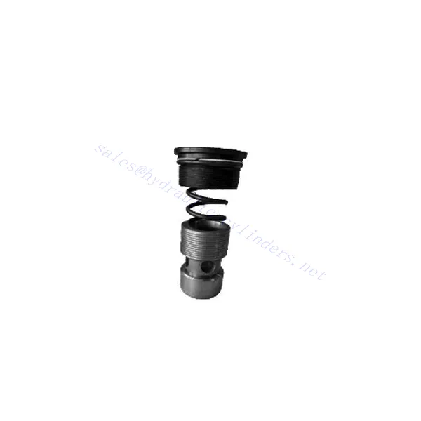
M-SR Series Check Hydraulic Valve Cartridge

The M-SR series check hydraulic valve cartridge is versatile and essential in hydraulic systems. This valve cartridge is designed to regulate fluid flow and prevent backflow and offers reliable performance, durability, and ease of installation.
The M-SR series check hydraulic valve cartridge is a reliable and efficient solution for fluid control in hydraulic systems. With efficient check valve functionality, compact design, high flow capacity, and robust construction, this valve cartridge ensures optimal system performance, prevents backflow, and enhances overall efficiency. By following the recommended usage methods and maintenance practices, the M-SR series check hydraulic valve cartridge delivers reliable operation and extends the lifespan of hydraulic systems. Upgrade your hydraulic system with the m-sr series check hydraulic valve cartridge and experience efficient and reliable fluid control.
M-SR Series Check Hydraulic Valve Cartridge Key Characteristics:
- Efficient Check Valve Functionality:
- The M-SR series valve cartridge features a built-in check valve mechanism that enables the unidirectional flow of hydraulic fluid.
- It effectively prevents backflow and ensures fluid flows in the desired direction, minimizing the risk of system damage and inefficiency.
- Compact and Versatile Design:
- The valve cartridge is compact, making it suitable for applications with limited space or where weight considerations are crucial.
- Its versatile design allows easy integration into various hydraulic systems, including mobile machinery, industrial equipment, and hydraulic power units.
- Elevata capacità di flusso:
- Despite its compact size, the M-SR series valve cartridge offers high flow capacity, allowing for efficient fluid transfer and system performance.
- It minimizes pressure drops, ensuring optimal hydraulic power delivery to actuators and other components.
- Costruzione robusta:
- Constructed from high-quality materials, the M-SR series valve cartridge demonstrates excellent durability and resistance to wear and corrosion.
- It is designed to withstand demanding operating conditions, prolonging the valve cartridge’s lifespan and reducing maintenance requirements.
M-SR Series Check Hydraulic Valve Cartridge Parameter:
| Specifiche | sbarra | NG6-30 | |||||
| Pressione massima di esercizio | sbarra | 315 | |||||
| pressione di rottura | sbarra | Fare riferimento alla curva caratteristica | |||||
| Portata massima | litri/min | Fare riferimento alla curva caratteristica | |||||
| intervallo di viscosità | mm2/S | da 2,8 a 380 | |||||
| Intervallo di temperatura del fluido | °C | -30 to +80(NBR seals) | |||||
| -20 a +80 (guarnizioni FKM) | |||||||
| Fluido | Olio minerale adatto per guarnizioni NBR e FKM | ||||||
| Estere fosfatico per guarnizione FKM | |||||||
| Grado di contaminazione | Grado massimo consentito di contaminazione del fluido: Classe 9. NAS 1638 o 20/18/15, ISO4406 | ||||||
| Misurare | 8 | 10 | 15 | 20 | 25 | 30 | |
| Weight: Right angled check valve cartridge | kg | 0.03 | 0.05 | 0.08 | 0.14 | 0.32 | 0.47 |
M-SR Series Check Hydraulic Valve Cartridge Advantages:
NG6-30
• Utilizzato nell'installazione del blocco del percorso dell'olio
• Leak-free closure
• Various opening pressures available (see model description)
Usage Method Of M-SR Series Check Hydraulic Valve Cartridge:
- Analisi del sistema:
- Before installation, thoroughly analyze the hydraulic system to determine the specific requirements and operational parameters.
- Consider factors such as flow rates, pressure ratings, and compatibility with the M-SR series valve cartridge.
- Selezione della valvola:
- Select the appropriate M-SR series valve cartridge variant based on the system requirements and specifications.
- Consider factors like flow capacity, pressure ratings, and compatibility with other system components.
- Installazione:
- Follow the manufacturer’s instructions for properly installing the M-SR series valve cartridge in the hydraulic system.
- Ensure a secure fit within the valve cavity, proper alignment with the fluid flow path, and appropriate sealing to prevent leaks.
- Fluid Flow Direction:
- Ensure the M-SR Series Valve Cartridge is installed in the correct orientation, allowing for the desired fluid flow direction.
- Align the valve cartridge with the system’s flow path, ensuring proper engagement of the check valve mechanism.
How Does A Hydraulic Diverter Valve Work?
A hydraulic diverter valve is a key component in hydraulic systems that allows the operator to redirect hydraulic fluid flow from one path to another. It provides flexibility in controlling the flow direction and enables the use of multiple hydraulic actuators with a single hydraulic power source. Here’s a breakdown of how a hydraulic diverter valve works:
- Struttura della valvola:
- A hydraulic diverter valve typically consists of a valve body with multiple ports, a movable spool or ball, and actuators such as levers, solenoids, or pilot pressure mechanisms.
- The valve body contains internal passages and chambers that direct the flow of hydraulic fluid.
- Fluid Flow Paths:
- The diverter valve has multiple ports that connect to different hydraulic components in the system, such as the pump, reservoir, actuators, and other valves.
- These ports include an inlet port, outlet ports, and work ports, each serving a specific purpose in controlling the fluid flow.
- Spool or Ball:
- The valve body houses a movable spool or ball that controls the flow of hydraulic fluid.
- The spool can slide within the valve body, while the ball can rotate or move linearly to open or close specific passages.
- Actuation Mechanisms:
- Hydraulic diverter valves can be actuated manually, electrically, or hydraulically, depending on the specific design and application requirement.
- Manual actuation involves levers or handles that the operator physically moves to position the spool or ball.
- Electrical actuation utilizes solenoids that receive electrical signals to shift the spool or ball, allowing for remote control and automation.
- Hydraulic actuation employs pilot pressure to move the spool or ball, often in conjunction with electrical or manual control.
- Posizioni delle valvole:
- Depending on the valve design, there are typically multiple positions that the spool or ball can assume, each corresponding to a specific flow path.
- Common positions include neutral, where all ports are blocked, and various actuating positions that allow flow between specific ports.
- As the spool or ball shifts, it aligns with specific ports, opening or closing passages and directing the hydraulic fluid accordingly.
- Operator Input:
- The operator engages the hydraulic diverter valve by actuating the manual lever, applying electrical signals to solenoids, or manipulating pilot pressure.
- This input determines the desired valve position, which in turn determines the flow direction and the action of the hydraulic actuators.
- Funzionamento del sistema:
- Once the hydraulic diverter valve is in the desired position, hydraulic fluid flows through the appropriate passages and ports.
- This flow of fluid can be directed to different hydraulic actuators, allowing for selective control of the actuator’s movement or operation.
Capacità e capacità della fabbrica:
(1) Montaggio
Disponiamo di una piattaforma di assemblaggio indipendente di ricerca e sviluppo di prima classe. L'officina di produzione di cilindri idraulici dispone di quattro linee di assemblaggio semiautomatiche per cilindri di sollevamento e una linea di assemblaggio automatica per cilindri di inclinazione, con una capacità produttiva annua progettata di 1 milione di pezzi. L'officina per cilindri speciali è dotata di un sistema di assemblaggio semiautomatico per la pulizia con diverse specifiche, con una capacità produttiva annua progettata di 200.000 pezzi e dotata di rinomate macchine per lavorazioni meccaniche CNC, un centro di lavoro, attrezzature speciali per la lavorazione di cilindri ad alta precisione, una macchina per saldatura robotizzata, una macchina per la pulizia automatica, una macchina per l'assemblaggio automatico dei cilindri e una linea di produzione per la verniciatura automatica. Sono disponibili oltre 300 set di attrezzature critiche. L'allocazione ottimale e l'uso efficiente delle risorse delle attrezzature garantiscono i requisiti di precisione dei prodotti e ne soddisfano le elevate esigenze di qualità.


(2) Lavorazione
L'officina di lavorazione è dotata di un centro di tornitura su rotaia inclinata personalizzato, di un centro di lavorazione, di una levigatrice ad alta velocità, di un robot di saldatura e di altre attrezzature correlate, in grado di gestire la lavorazione di tubi cilindrici con un diametro interno massimo di 400 mm e una lunghezza massima di 6 metri.


(3) Saldatura


(4) Verniciatura e rivestimento
Con linee automatiche di verniciatura a base d'acqua a cilindro di piccole e medie dimensioni, per realizzare il carico e lo scarico automatico con robot e la spruzzatura automatica, la capacità di progettazione è di 4000 pezzi per turno;
Disponiamo anche di una linea di produzione semiautomatica di vernici per cilindri di grandi dimensioni alimentata da una catena di potenza, con una capacità di progettazione di 60 casse per turno.


(5) Test
Disponiamo di strutture di ispezione e banchi di prova di prim'ordine per garantire che le prestazioni del cilindro siano conformi ai requisiti.


Siamo uno dei migliori produttori di cilindri idraulici. Offriamo una gamma completa di cilindri idraulici. Forniamo anche i relativi componenti. riduttori agricoliAbbiamo esportato i nostri prodotti a clienti in tutto il mondo e ci siamo guadagnati un'ottima reputazione grazie alla qualità superiore dei nostri prodotti e al servizio post-vendita. Invitiamo i clienti nazionali e internazionali a contattarci per negoziare affari, scambiare informazioni e collaborare con noi!