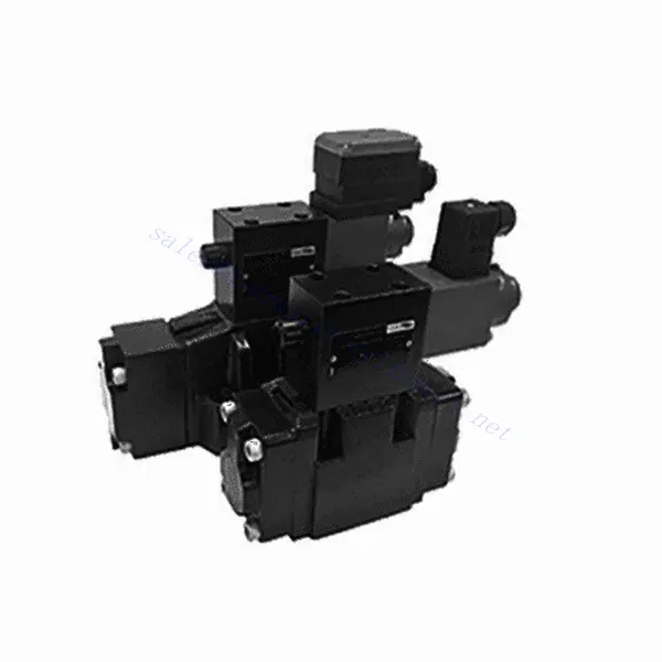
3DRE/M(E) Series 3-way Pilot Operated Proportional Pressure Reducing Hydraulic Valve
3DRE/M(E) Series 3-way Pilot Operated Proportional Pressure Reducing Hydraulic Valve
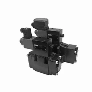
The 3DRE/M(E) series 3-way pilot-operated proportional pressure-reducing hydraulic valve is a cutting-edge hydraulic component designed to deliver accurate pressure control in hydraulic systems. With its advanced pilot-operated proportional control technology, this valve ensures precise regulation, efficient performance, and reliable operation.
The 3DRE/M(E) series 3-way proportional pressure-reducing hydraulic valve empowers hydraulic systems with precise pressure control, efficiency, and reliable performance. With its advanced proportional control technology and 3-way configuration, this valve offers versatility and flexibility in pressure regulation across different hydraulic circuits. By following the recommended usage methods and maintenance guidelines, you can maximize the benefits and longevity of the 3DRE/M(E) series valve, optimizing pressure control and overall performance in your hydraulic system. Upgrade your hydraulic setup today and experience superior pressure regulation with the 3DRE/M(E) series 3-way proportional pressure-reducing hydraulic valve.
3DRE/M(E) Series 3-way Pilot Operated Proportional Pressure Reducing Hydraulic Valve Key Characteristics:
- პროპორციული წნევის კონტროლი:
- The 3DRE/M(E) series valve offers precise and proportional pressure control, enabling dynamic adjustment of hydraulic pressure levels.
- This feature ensures accurate pressure regulation, maintaining a consistent and safe pressure within the hydraulic system.
- პილოტური დიზაინი:
- With its pilot-operated design, the valve delivers enhanced precision and responsiveness in pressure control.
- It utilizes a pilot valve to modulate the main valve, allowing for precise adjustments and improved control over pressure reduction.
- 3-way Configuration:
- The 3DRE/M(E) series valve features a versatile 3-way configuration, providing flexibility in controlling pressure across different hydraulic circuits.
- It allows for simultaneous pressure reduction in one circuit while supplying pressure to another course.
- ეფექტური შესრულება:
- By utilizing advanced proportional control technology, the valve ensures efficient performance, optimizing energy usage and reducing operational costs.
- It minimizes pressure fluctuations, enhancing system efficiency and contributing to overall productivity.
3DRE/M(E) Series 3-way Pilot Operated Proportional Pressure Reducing Hydraulic Valve Parameter:
| ჰიდრავლიკური | ||||||||
| ინსტალაციის პოზიცია | სურვილისამებრ, სასურველია ჰორიზონტალური | |||||||
| ზომა | 6 | 10 | ||||||
| წონა | 4WRA…L2X | კგ | 2 | 6.6 | ||||
| 4WRAE…L2X | 2.2 | 6.8 | ||||||
| ნომინალური ნაკადის qnom, როდესაც Δp = 10 ბარი | ლ/წთ | 7, 15, 26 | 30, 60 | |||||
| ჰისტერეზისი | % | ≤5 | ||||||
| განმეორებადობა | % | ≤1 | ||||||
| რეაქციის მგრძნობელობა | % | ≤0.5 | ||||||
| მაქსიმალური სამუშაო წნევა | პორტის ABP | ბარი | 315 | |||||
| პორტი T | ბარი | 210 | ||||||
| სითხე | მინერალური ზეთი, შესაფერისი NBR და FKM დალუქვისთვის | |||||||
| ფოსფატის ეთერი FKM დალუქვისთვის | ||||||||
| სითხის ტემპერატურის დიაპაზონი | 4WRA…L2X | ℃ | -20℃-დან 70℃-მდე (-4°F-დან 158°F-მდე) | |||||
| 4WRAE…L2X | ℃ | -20℃-დან 50℃-მდე (-4° F-დან 122° F-მდე) | ||||||
| სიბლანტის დიაპაზონი | მმ²/წმ | 20-დან 380-მდე (სასურველია 30-დან 46-მდე) | ||||||
| დაბინძურების ხარისხი | NAS1638 კლასი 9 ან ISO 4406 კლასი 20/18/15 | |||||||
| ელექტრო მონაცემები | ||||||||
| 1) სოლენოიდი | ||||||||
| ძაბვის ტიპი | ვაშინგტონი | |||||||
| ბრძანების მნიშვნელობის სიგნალი | ±10 ვ ან 4~20 მA | |||||||
| მაქსიმალური დენი თითო სოლენოიდზე | ა | 2.5 | 1.5 | 0.8 | ||||
| ხვეულის წინააღმდეგობა | ცივი ღირებულება | ომეგა | 2 | 4.8 | 19.5 | |||
| მაქსიმალური სითბოს მნიშვნელობა | 3 | 7.2 | 28.8 | |||||
| მოვალეობა | % | ED100% | ||||||
| ხვეულის ტემპერატურა | ℃ | 150 | ||||||
| სარქვლის დაცვა EN 60529 სტანდარტის შესაბამისად | IP 65 | |||||||
| 2) მართვის ელექტრონიკა | ||||||||
| ამპილფიერი | 4WRA…L2X | VT-VSPA2-L2X | ||||||
| 4WRAE…L2X | ინტეგრირებულია სარქველში (OBE) | |||||||
| ოპერაციული ძაბვა | ნომინალური ძაბვა | VDC | 24 | |||||
| ქვედა ზღვრული მნიშვნელობა | ვ | 21/22 (4WRA), 19 (4WRAE) | ||||||
| ზედა ზღვრული მნიშვნელობა | ვ | 35 | ||||||
| გამაძლიერებლის მიმდინარე მოხმარება | იმაქსი | ა | <1.8 | |||||
| იმაქსი | ა | 3 | ||||||
3DREP(E) Series 3-way Proportional Pressure Reducing Hydraulic Valve Advantages:
• The pilot-operated relief valve is used for the pressure reduction from P to A and the overflow function from A to T.
• Used for bottom sub-plate mounting, driven by proportional solenoid.
• The mounting surface is in accordance with DIN24 340, type A, ISO4401 and CETOP-RP 121H
• The maximum safety pressure is available for selection.
• Spool spring alignmentalignment
• 3DRE electronic controller: european card specification amplifier VT-VSPA1-1/VT-VSPD-1
• Set point the pressure characteristic curve is linear
• 3DRE(M)E series integrated electronic controller
• Setting value caused by manufacturing error-the deviation of the pressure characteristic curve is small
• The slope of the pressure increase and decrease can be adjusted independently
Usage Method Of 3DREP(E) Series 3-way Proportional Pressure Reducing Hydraulic Valve:
- სისტემის შეფასება:
- Evaluate your hydraulic system and identify the specific pressure control requirements for each circuit.
- Determine if the 3DRE/M(E) series valve is suitable based on its pressure range, flow capacity, and compatibility with your system.
- სარქვლის შერჩევა:
- Select the appropriate variant of the 3DRE/M(E) series valve based on your system parameters, pressure range, and flow requirements.
- გაითვალისწინეთ მაქსიმალური წნევის ნომინალური მაჩვენებელი, რეაგირების დრო და ოპერაციული პირობები.
- ინსტალაცია:
- ყურადღებით მიჰყევით მწარმოებლის ინსტალაციის ინსტრუქციებს, უზრუნველყავით სარქვლის სწორი გასწორება და უსაფრთხოდ დამაგრება.
- შეაერთეთ სარქველი ჰიდრავლიკურ სისტემასთან, უზრუნველყავით გაჟონვისგან თავისუფალი კავშირები და ნაკადის მიმართულების სწორი გასწორება.
- წნევის რეგულირება:
- Utilize the pilot valve control mechanism provided with the 3DRE/M(E) series valve to adjust the desired pressure reduction level for each circuit.
- Gradually adjust the pilot valve control to achieve the desired pressure control, monitoring the pressure gauge readings and system response.
How To Adjust Hydraulic Valves?
Adjusting hydraulic valves is a crucial task to ensure proper flow control and system performance in hydraulic applications. Here’s a step-by-step guide on how to adjust hydraulic valves:
- სარქვლის იდენტიფიცირება:
- Determine the type of hydraulic valve you need to adjust: pressure relief valve, flow control valve, directional control valve, or any other type.
- Locate the valve within your hydraulic system. It can be positioned near the pump, in the control valve manifold, or within specific hydraulic components.
- შეაგროვეთ საჭირო ინსტრუმენტები:
- Before starting the adjustment process, gather the required tools, such as an adjustable wrench, a screwdriver, a pressure gauge (if applicable), and any specialized tools recommended by the valve manufacturer.
- Understand the Valve Function:
- Familiarize yourself with the purpose and function of the valve you are adjusting. Refer to the valve’s technical documentation or consult the manufacturer’s guidelines for specific details.
- Determine the Desired Setting:
- Identify the desired setting or parameter you want to achieve by adjusting the valve. This could be pressure, flow rate, direction, or any other adjustable parameter based on the valve type.
- Preliminary Checks:
- Ensure that the hydraulic system is depressurized before attempting any adjustments. This can be done by shutting down the system and relieving residual pressure through appropriate valves.
- Access the Adjustment Mechanism:
- Locate the adjustment mechanism on the valve. It can be a set screw, locknut, knob, or other similar devices depending on the valve type.
- Some valves may require removing a protective cap or cover to access the adjustment mechanism.
- თანდათანობითი კორექტირების განხორციელება:
- Using the appropriate tool, make small incremental adjustments to the valve according to the desired setting.
- Follow the manufacturer’s guidelines to determine the direction (clockwise or counterclockwise) and the amount of adjustment required.
- Make gradual adjustments and periodically check the system’s response to ensure you are moving in the desired direction.
- Test and Monitor:
- After each adjustment, activate the hydraulic system and observe its performance.
- Use appropriate measurement tools (pressure gauge, flow meter, etc.) to verify that the valve is operating within the desired range.
- Monitor the system for any abnormalities or unexpected behavior. If necessary, make further adjustments to fine-tune the valve setting.
- Lock the Adjustment (if applicable):
- Once you achieve the desired setting, secure the adjustment mechanism to prevent unintended changes.
- This can be done by tightening a locknut, securing a set screw, or using any other method recommended by the valve manufacturer.
ქარხნის შესაძლებლობები და სიმძლავრე:
(1) აწყობა
ჩვენ გვაქვს პირველი კლასის დამოუკიდებელი კვლევისა და განვითარების აწყობის პლატფორმა. ჰიდრავლიკური ცილინდრების წარმოების სახელოსნოს აქვს ოთხი ნახევრად ავტომატური ამწევი ცილინდრების აწყობის ხაზი და ერთი ავტომატური დახრილი ცილინდრების აწყობის ხაზი, რომელთა წლიური წარმოების მოცულობა 1 მილიონი ცალია. სპეციალური ცილინდრების სახელოსნო აღჭურვილია სხვადასხვა სპეციფიკაციის ნახევრად ავტომატური საწმენდი აწყობის სისტემით, რომლის წლიური წარმოების მოცულობა 200,000 ცალია და აღჭურვილია ცნობილი CNC დამუშავების აღჭურვილობით, დამუშავების ცენტრით, მაღალი სიზუსტის ცილინდრების დამუშავების სპეციალური აღჭურვილობით, რობოტ-შედუღების დანადგარით, ავტომატური საწმენდი დანადგარით, ავტომატური ცილინდრების აწყობის დანადგარით და ავტომატური შეღებვის წარმოების ხაზით. არსებული კრიტიკული აღჭურვილობა 300-ზე მეტი კომპლექტით (კომპლექტით) შედგება. აღჭურვილობის რესურსების ოპტიმალური განაწილება და ეფექტური გამოყენება უზრუნველყოფს პროდუქციის სიზუსტის მოთხოვნებს და აკმაყოფილებს პროდუქციის მაღალი ხარისხის საჭიროებებს.


(2) დამუშავება
დამუშავების საამქრო აღჭურვილია ინდივიდუალურად მორგებული დახრილი რელსების შემობრუნების ცენტრით, დამუშავების ცენტრით, მაღალსიჩქარიანი დამუშავების დანადგარით, შედუღების რობოტით და სხვა დაკავშირებული აღჭურვილობით, რომელსაც შეუძლია ცილინდრული მილების დამუშავება მაქსიმალური შიდა დიამეტრით 400 მმ და მაქსიმალური სიგრძით 6 მეტრი.

(3) შედუღება

(4) შეღებვა და საფარი
მცირე და საშუალო ზომის ცილინდრიანი ავტომატური წყალზე დაფუძნებული საღებავის საფარის ხაზებით, ავტომატური რობოტის ჩატვირთვა-გადმოტვირთვისა და ავტომატური შესხურების მისაღწევად, ცვლაში 4000 ცალი დიზაინის ტევადობით;
ჩვენ ასევე გვაქვს ელექტრო ჯაჭვით მომუშავე ნახევრად ავტომატური საღებავის წარმოების ხაზი დიდი ცილინდრებისთვის, ცვლაში 60 ყუთის დამუშავების საპროექტო სიმძლავრით.


(5) ტესტირება
ჩვენ გვაქვს პირველი კლასის შემოწმების ობიექტები და სატესტო ცენტრები, რათა უზრუნველვყოთ, რომ ცილინდრის მუშაობა აკმაყოფილებს მოთხოვნებს.

ჩვენ ვართ ერთ-ერთი საუკეთესო ჰიდრავლიკური ცილინდრების მწარმოებელი. ჩვენ შეგვიძლია შემოგთავაზოთ ჰიდრავლიკური ცილინდრების ყოვლისმომცველი ნაკრები. ჩვენ ასევე ვთავაზობთ შესაბამის... სასოფლო-სამეურნეო გადაცემათა კოლოფიჩვენ ჩვენი პროდუქცია მსოფლიოს მასშტაბით კლიენტებისთვის ექსპორტირებული გვაქვს და კარგი რეპუტაცია დავიმსახურეთ ჩვენი უმაღლესი ხარისხისა და გაყიდვის შემდგომი მომსახურების წყალობით. ჩვენ მივესალმებით როგორც ადგილობრივ, ასევე საზღვარგარეთელ მომხმარებლებს, რომლებიც დაგვიკავშირდებიან ბიზნესთან დაკავშირებით მოლაპარაკებების, ინფორმაციის გაცვლისა და ითანამშრომლეთ ჩვენთან!