DR სერიის პილოტური ოპერირებადი წნევის შემამცირებელი ჰიდრავლიკური სარქველი
როგორც ჰიდრავლიკური ცილინდრების ერთ-ერთი მწარმოებელი, მიმწოდებელი და მექანიკური პროდუქტების ექსპორტიორი, ჩვენ გთავაზობთ ჰიდრავლიკურ ცილინდრებს და სხვა მრავალ პროდუქტს.
დეტალებისთვის გთხოვთ დაგვიკავშირდეთ.
ფოსტა:sales@hydraulic-cylinders.net
ჰიდრავლიკური ცილინდრების მწარმოებელი და მიმწოდებელი ექსპორტიორი.
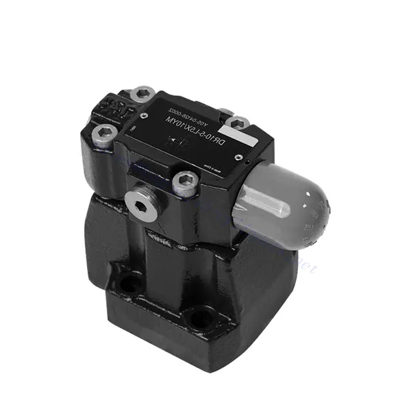
DR სერიის პილოტური ოპერირებადი წნევის შემამცირებელი ჰიდრავლიკური სარქველი
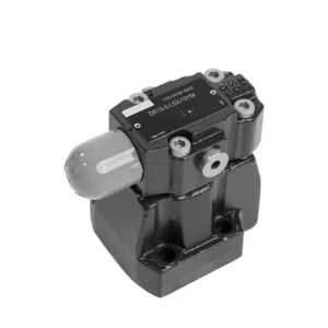
DR სერიის პილოტური წნევის შემამცირებელი ჰიდრავლიკური სარქველი წარმოადგენს მაღალი ხარისხის და საიმედო კომპონენტს, რომელიც შექმნილია ჰიდრავლიკურ სისტემებში წნევის ზუსტი კონტროლის უზრუნველსაყოფად. თავისი ინოვაციური პილოტური მექანიზმითა და განსაკუთრებული მუშაობით, ეს სარქველი ზუსტად ამცირებს ჰიდრავლიკურ წნევას სისტემის სპეციფიკური მოთხოვნების დასაკმაყოფილებლად.
DR სერიის პილოტური წნევის შემამცირებელი ჰიდრავლიკური სარქველი წარმოადგენს მაღალი ხარისხის გადაწყვეტას ჰიდრავლიკურ სისტემებში წნევის ზუსტი კონტროლისთვის. პილოტური დიზაინით, ზუსტი წნევის კონტროლით, ფართო წნევის დიაპაზონით და მაღალი ნაკადის ტევადობით, ეს სარქველი უზრუნველყოფს წნევის ეფექტურ და ზუსტ შემცირებას, ამავდროულად იცავს სისტემის კომპონენტებს. რეკომენდებული გამოყენების მეთოდებისა და მოვლა-პატრონობის პრაქტიკის დაცვით, DR სერიის სარქველი უზრუნველყოფს საიმედო მუშაობას, რაც ახანგრძლივებს ჰიდრავლიკური სისტემების სიცოცხლის ხანგრძლივობას. განაახლეთ თქვენი ჰიდრავლიკური სისტემა dr სერიის პილოტური წნევის შემამცირებელი ჰიდრავლიკური სარქველით და ისიამოვნეთ ოპტიმალური წნევის კონტროლით სისტემის ეფექტურობისა და პროდუქტიულობის გასაუმჯობესებლად.
DR სერიის პილოტური ოპერირებადი წნევის შემამცირებელი ჰიდრავლიკური სარქვლის ძირითადი მახასიათებლები:
- პილოტის მიერ მართული დიზაინი:
- DR სერიის სარქველს აქვს პილოტური მართვითი დიზაინი, რომელიც უზრუნველყოფს ჰიდრავლიკურ სისტემებში წნევის ზუსტ, საიმედო და სტაბილურ შემცირებას.
- ის იყენებს ცალკეულ მართვის წრედს, საპილოტე წრედს, მთავარი სარქვლის გახსნის რეგულირებისა და წნევის კონტროლისთვის.
- ზუსტი წნევის კონტროლი:
- ეს სარქველი უზრუნველყოფს წნევის კონტროლის განსაკუთრებულ სიზუსტეს, რაც საშუალებას აძლევს ჰიდრავლიკურ სისტემებს იმუშაონ სასურველი წნევის ლიმიტებში.
- ის ინარჩუნებს წნევის მუდმივ დონეს, ხელს უშლის ზედმეტ წნევას და იცავს სისტემის მგრძნობიარე კომპონენტებს.
- ფართო წნევის დიაპაზონი:
- DR სერიის სარქველი ხელმისაწვდომია სხვადასხვა წნევის დიაპაზონში, რაც მას სხვადასხვა ჰიდრავლიკური გამოყენებისთვის შესაფერისს ხდის.
- ეს საშუალებას გაძლევთ შეცვალოთ სისტემა კონკრეტული მოთხოვნების შესაბამისად და ოპტიმიზაცია გაუკეთოთ მის მუშაობას.
- მაღალი ნაკადის ტევადობა:
- ეს სარქველი გამოირჩევა შესანიშნავი ნაკადის გამტარუნარიანობით, რაც მას საშუალებას აძლევს გაუმკლავდეს მაღალ ნაკადის სიჩქარეს წნევის კონტროლის სიზუსტის შემცირების გარეშე.
- ის უზრუნველყოფს სითხის ეფექტურ რეგულირებას და სისტემის შეუფერხებელ მუშაობას.
DR სერიის პილოტური ოპერირებადი წნევის შემცირების ჰიდრავლიკური სარქვლის პარამეტრი:
| სითხე | მინერალური ზეთი, შესაფერისი NBR და FKM დალუქვისთვის | |||||||
| ფოსფატის ეთერი FKM დალუქვისთვის | ||||||||
| სითხის ტემპერატურის დიაპაზონი | ℃ | -30-დან +80-მდე (NBR საკეტები) | ||||||
| -20-დან +80-მდე (FKM საკეტები) | ||||||||
| სიბლანტის დიაპაზონი | მმ2/წმ | 10-დან 800-მდე | ||||||
| დაბინძურების ხარისხი | სითხის დაბინძურების მაქსიმალური დასაშვები ხარისხი: კლასი 9. NAS 1638 ან 20/18/15, ISO4406 | |||||||
| მაქსიმალური სამუშაო წნევა | პორტი B | ბარი | 350 | |||||
| სამუშაო წნევის დიაპაზონი | პორტი A | ბარი | 10-დან 350-მდე | |||||
| მაქსიმალური საყრდენი წნევა | პორტი Y | ბარი | 350 (მხოლოდ უკუსაკონტროლო სარქვლის გარეშე); 315 (უკუსაკონტროლო სარქველით) | |||||
| წნევის დაყენება | მაქს. | ბარი | 50;100;200;315;350 | |||||
| მინ. | ბარი | ნაკადის სიჩქარესთან დაკავშირებული (იხილეთ დამახასიათებელი მრუდი) | ||||||
| ზომა | DR10 | DR15 | DR20 | DR25 | DR30 | |||
| მაქსიმალური ნაკადის სიჩქარე | ბაზის ქვეფირფიტის მონტაჟი | ლ/წთ | 150 | – | 300 | – | 400 | |
| ხრახნიანი კავშირი | ლ/წთ | 150 | 300 | 300 | 400 | 400 | ||
| ინსტალაციის პოზიცია | ინსტალაციის პოზიცია | |||||||
| ზომა | DR10 | DR15 | DR20 | DR25 | DR30 | |||
| წონა | ბაზის ქვეფირფიტის მონტაჟი | DR | კგ | დაახლოებით 3.6 | – | დაახლოებით 5.3 | – | დაახლოებით 8.2 |
| ხრახნიანი კავშირი | DR…G | კგ | დაახლოებით 5.3 | დაახლოებით 5.5 | დაახლოებით 5.1 | დაახლოებით 5.0 | დაახლოებით 5.0 | |
| კონგოს დემოკრატიული რესპუბლიკა | კგ | დაახლოებით 1.2 | ||||||
| DRC30 | კგ | დაახლოებით 1.5 | ||||||
DR სერიის პილოტური ოპერირებადი წნევის შემცირების ჰიდრავლიკური სარქვლის უპირატესობები:
• გამოიყენება ქვედა ქვეფირფიტის დასამონტაჟებლად
• სამონტაჟო ზედაპირი შეესაბამება DIN24340 D-სა და ISO5781-ს
• გამოიყენება ნავთობის გზის ბლოკის მონტაჟში
• გამოიყენება ხრახნიანი შეერთებისას
• ხუთი წნევის დიაპაზონი
• ორი ტიპის რეგულირება: სახელური, დამცავი თავსახურით რეგულირებადი ხრახნი
• სურვილისამებრ ერთმიმართულებიანი სარქველი (გამოიყენება მხოლოდ ქვედა ქვეფირფიტის დასამონტაჟებლად)
DR სერიის პილოტური ოპერირების წნევის შემცირების ჰიდრავლიკური სარქვლის გამოყენების მეთოდი :
- სისტემის ანალიზი:
- ჩაატარეთ ჰიდრავლიკური სისტემის ყოვლისმომცველი ანალიზი წნევის კონტროლის კონკრეტული მოთხოვნების დასადგენად.
- გაითვალისწინეთ მაქსიმალური სამუშაო წნევა, სასურველი წნევის დიაპაზონი და ნაკადის სიჩქარე.
- სარქვლის შერჩევა:
- სისტემის წნევის კონტროლის სპეციფიკაციების მიხედვით, აირჩიეთ DR სერიის შესაბამისი სარქვლის ვარიანტი.
- გაითვალისწინეთ წნევის ნომინალური მაჩვენებელი, ნაკადის გამტარუნარიანობა და თავსებადობა სისტემის სხვა კომპონენტებთან.
- ინსტალაცია:
- ჰიდრავლიკური სისტემის DR სერიის პილოტური წნევის შემამცირებელი სარქვლის სწორად დასაყენებლად მიჰყევით მწარმოებლის ინსტრუქციებს.
- გაჟონვის თავიდან ასაცილებლად და მუშაობის ოპტიმიზაციისთვის უზრუნველყავით სათანადო გასწორება და უსაფრთხო კავშირები.
- კალიბრაცია:
- სასურველი წნევის დასაყენებლად დააკალიბრეთ სარქველი.
- გამოიყენეთ წნევის საზომი ხელსაწყოები ან სხვა საზომი მოწყობილობები სარქვლის საპილოტე წრედის ზუსტად დასარეგულირებლად.
როგორ მუშაობს ჰიდრავლიკური გამტარი სარქველი?
ჰიდრავლიკური გამტარი სარქველი ჰიდრავლიკური სისტემების მნიშვნელოვანი კომპონენტია, რომელიც იცავს სისტემას ჭარბი წნევისგან ჭარბი სითხის ნაკადის რეზერვუარში უკან გადამისამართებით. ის მუშაობს სისტემაში წნევის დონის გასაკონტროლებლად ზამბარიანი მექანიზმის გამოყენების პრინციპის საფუძველზე. მოდით განვიხილოთ, თუ როგორ მუშაობს ჰიდრავლიკური გამტარი სარქველი:
- სარქვლის კონსტრუქცია:
- ჰიდრავლიკური განმუხტვის სარქველი შედგება სარქვლის კორპუსის, ზამბარიანი კონუსის ან კოჭის და რეგულირებადი ზამბარისგან.
- სარქვლის კორპუსი შეიცავს სითხის პორტებს შესასვლელი, გამოსასვლელი და რეზერვუარში დრენაჟის ან დაბრუნების მილისთვის.
- წნევის პარამეტრი:
- შემზღუდველ სარქველს აქვს რეგულირებადი ზამბარა, რომელიც განსაზღვრავს წნევას, რომლის დროსაც სარქველი იხსნება.
- ზამბარის დაჭიმულობის რეგულირებით შესაძლებელია წნევის დაყენება სარქვლის გასახსნელად და ზედმეტი დაძაბულობის მოსახსნელად.
- სისტემის წნევის მონიტორინგი:
- ჰიდრავლიკური სისტემის მუშაობისას წნევა იზრდება ისეთი ფაქტორების გამო, როგორიცაა ტუმბოს სიმძლავრე, დატვირთვის წინააღმდეგობა ან ტემპერატურის ცვლილებები.
- შემშვები სარქველი მუდმივად აკონტროლებს სისტემის წნევას მისი შესასვლელი პორტის მეშვეობით.
- წნევის ზღვარი:
- როდესაც სისტემის წნევა მიაღწევს ან გადააჭარბებს დადგენილ წნევის ზღურბლს, პოპეტზე ან კოჭაზე ზამბარის დაჭიმულობის საწინააღმდეგო ძალა მოქმედებს.
- სარქვლის გახსნა:
- როგორც კი სისტემის წნევის მიერ მოქმედი ძალა გადააჭარბებს ზამბარის დაჭიმულობას, გამტარი სარქველი იხსნება.
- ეს ქმნის გზას ჭარბი სითხისთვის, რათა სისტემის მაღალი წნევის მხრიდან დაბალი წნევის მხარეს ან პირდაპირ რეზერვუარში დაბრუნდეს.
- წნევის გათანაბრება:
- შემშვები სარქველი გადამისამართებს ჭარბი სითხის ნაკადს, რაც საშუალებას იძლევა სისტემაში წნევის გათანაბრება და ზედმეტი წნევის თავიდან აცილება.
- ეს იცავს სისტემის კომპონენტებს შესაძლო დაზიანებისგან და უზრუნველყოფს უსაფრთხო მუშაობას.
- სარქვლის დახურვა:
- როგორც კი წნევა დადგენილ ზღურბლზე დაბლა დაეცემა, ზამბარის დაჭიმულობა გადალახავს სისტემის წნევის მიერ განხორციელებულ ძალას.
- რელიეფური სარქველი იხურება, ბლოკავს სითხის ნაკადის გზას და აღადგენს ჰიდრავლიკური სითხის ნორმალურ ნაკადს სისტემაში.
- უწყვეტი მონიტორინგი:
- შემშვები სარქველი განუწყვეტლივ აკონტროლებს სისტემის წნევას, საჭიროებისამებრ იხსნება და იხურება, რათა წნევა სასურველ დიაპაზონში შენარჩუნდეს.
- ეს დინამიური რეაქცია უზრუნველყოფს სისტემის უსაფრთხო მუშაობას და ხელს უშლის წნევის მკვეთრ მატებას ან რყევებს.
ქარხნის შესაძლებლობები და სიმძლავრე:
(1) აწყობა
ჩვენ გვაქვს პირველი კლასის დამოუკიდებელი კვლევისა და განვითარების აწყობის პლატფორმა. ჰიდრავლიკური ცილინდრების წარმოების სახელოსნოს აქვს ოთხი ნახევრად ავტომატური ამწევი ცილინდრების აწყობის ხაზი და ერთი ავტომატური დახრილი ცილინდრების აწყობის ხაზი, რომელთა წლიური წარმოების მოცულობა 1 მილიონი ცალია. სპეციალური ცილინდრების სახელოსნო აღჭურვილია სხვადასხვა სპეციფიკაციის ნახევრად ავტომატური საწმენდი აწყობის სისტემით, რომლის წლიური წარმოების მოცულობა 200,000 ცალია და აღჭურვილია ცნობილი CNC დამუშავების აღჭურვილობით, დამუშავების ცენტრით, მაღალი სიზუსტის ცილინდრების დამუშავების სპეციალური აღჭურვილობით, რობოტ-შედუღების დანადგარით, ავტომატური საწმენდი დანადგარით, ავტომატური ცილინდრების აწყობის დანადგარით და ავტომატური შეღებვის წარმოების ხაზით. არსებული კრიტიკული აღჭურვილობა 300-ზე მეტი კომპლექტით (კომპლექტით) შედგება. აღჭურვილობის რესურსების ოპტიმალური განაწილება და ეფექტური გამოყენება უზრუნველყოფს პროდუქციის სიზუსტის მოთხოვნებს და აკმაყოფილებს პროდუქციის მაღალი ხარისხის საჭიროებებს.


(2) დამუშავება
დამუშავების საამქრო აღჭურვილია ინდივიდუალურად მორგებული დახრილი რელსების შემობრუნების ცენტრით, დამუშავების ცენტრით, მაღალსიჩქარიანი დამუშავების დანადგარით, შედუღების რობოტით და სხვა დაკავშირებული აღჭურვილობით, რომელსაც შეუძლია ცილინდრული მილების დამუშავება მაქსიმალური შიდა დიამეტრით 400 მმ და მაქსიმალური სიგრძით 6 მეტრი.

(3) შედუღება

(4) შეღებვა და საფარი
მცირე და საშუალო ზომის ცილინდრიანი ავტომატური წყალზე დაფუძნებული საღებავის საფარის ხაზებით, ავტომატური რობოტის ჩატვირთვა-გადმოტვირთვისა და ავტომატური შესხურების მისაღწევად, ცვლაში 4000 ცალი დიზაინის ტევადობით;
ჩვენ ასევე გვაქვს ელექტრო ჯაჭვით მომუშავე ნახევრად ავტომატური საღებავის წარმოების ხაზი დიდი ცილინდრებისთვის, ცვლაში 60 ყუთის დამუშავების საპროექტო სიმძლავრით.


(5) ტესტირება
ჩვენ გვაქვს პირველი კლასის შემოწმების ობიექტები და სატესტო ცენტრები, რათა უზრუნველვყოთ, რომ ცილინდრის მუშაობა აკმაყოფილებს მოთხოვნებს.

ჩვენ ვართ ერთ-ერთი საუკეთესო ჰიდრავლიკური ცილინდრების მწარმოებელი. ჩვენ შეგვიძლია შემოგთავაზოთ ჰიდრავლიკური ცილინდრების ყოვლისმომცველი ნაკრები. ჩვენ ასევე ვთავაზობთ შესაბამის... სასოფლო-სამეურნეო გადაცემათა კოლოფიჩვენ ჩვენი პროდუქცია მსოფლიოს მასშტაბით კლიენტებისთვის ექსპორტირებული გვაქვს და კარგი რეპუტაცია დავიმსახურეთ ჩვენი უმაღლესი ხარისხისა და გაყიდვის შემდგომი მომსახურების წყალობით. ჩვენ მივესალმებით როგორც ადგილობრივ, ასევე საზღვარგარეთელ მომხმარებლებს, რომლებიც დაგვიკავშირდებიან ბიზნესთან დაკავშირებით მოლაპარაკებების, ინფორმაციის გაცვლისა და ითანამშრომლეთ ჩვენთან!
ჰიდრავლიკური ცილინდრის გამოყენება:
