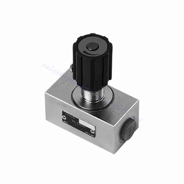
DV/DRV სერიის დროსელის და დროსელის შემოწმების ჰიდრავლიკური სარქველი
როგორც ჰიდრავლიკური ცილინდრების ერთ-ერთი მწარმოებელი, მიმწოდებელი და მექანიკური პროდუქტების ექსპორტიორი, ჩვენ გთავაზობთ ჰიდრავლიკურ ცილინდრებს და სხვა მრავალ პროდუქტს.
დეტალებისთვის გთხოვთ დაგვიკავშირდეთ.
ფოსტა:sales@hydraulic-cylinders.net
ჰიდრავლიკური ცილინდრების მწარმოებელი და მიმწოდებელი ექსპორტიორი.
DV/DRV სერიის დროსელის და დროსელის შემოწმების ჰიდრავლიკური სარქველი
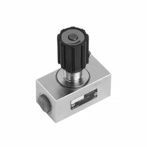
DV/DRV სერიის დროსელისა და დროსელის შემოწმების ჰიდრავლიკური სარქველი წარმოადგენს ულტრათანამედროვე ჰიდრავლიკურ კომპონენტს, რომელიც შექმნილია ჰიდრავლიკური სისტემების კონტროლისა და ეფექტურობის ოპტიმიზაციისთვის. მისი მოწინავე დროსელისა და დროსელის შემოწმების ფუნქციებით, ეს სარქველი გთავაზობთ ნაკადის ზუსტ კონტროლს და უზრუნველყოფს ჰიდრავლიკური აქტივატორების შეუფერხებელ მუშაობას.
DV/DRV სერიის დროსელისა და დროსელის შემოწმების ჰიდრავლიკური სარქველი წარმოადგენს მრავალმხრივ და საიმედო გადაწყვეტას ზუსტი ნაკადის კონტროლისა და სისტემის ეფექტურობის გასაუმჯობესებლად. მისი დროსელისა და დროსელის შემოწმების ფუნქციონალურობით, ნაკადის კონტროლის პერსონალიზების ვარიანტებითა და საიმედო მუშაობით, ეს სარქველი უზრუნველყოფს გამორჩეულ შედეგებს სხვადასხვა ჰიდრავლიკურ გამოყენებაში. რეკომენდებული გამოყენების მეთოდებისა და ტექნიკური მომსახურების ინსტრუქციების დაცვით, ოპერატორებს შეუძლიათ უზრუნველყონ DV/DRV სერიის დროსელისა და დროსელის შემოწმების ჰიდრავლიკური სარქვლის ხანგრძლივობა, საიმედოობა და ოპტიმალური ფუნქციონირება. განაახლეთ თქვენი ჰიდრავლიკური სისტემა ამ მოწინავე სარქველით და ისიამოვნეთ გაზრდილი ეფექტურობით, კონტროლითა და პროდუქტიულობით.
DV/DRV სერიის დროსელის და დროსელის შემოწმების ჰიდრავლიკური სარქვლის ძირითადი მახასიათებლები:
- დროსელის ფუნქციონირება:
- DV/DRV სერიის სარქველს აქვს დროსელის ფუნქცია, რომელიც ზუსტად არეგულირებს ჰიდრავლიკური სითხის ნაკადის სიჩქარეს.
- ის ოპერატორებს სითხის ნაკადის ზუსტ კონტროლს აძლევს, რაც საშუალებას აძლევს მათ დახვეწილად დაარეგულირონ აქტივატორის სიჩქარე და რეაგირება.
- დროსელის შემოწმების ფუნქცია:
- დროსელის კონტროლის გარდა, ეს სარქველი მოიცავს დროსელის შემოწმების ფუნქციას.
- დროსელის შემოწმების ფუნქცია სარქველს საკონტროლო სარქველად გარდაქმნის, რაც ხელს უშლის უკუდინებას და ინარჩუნებს სისტემის სტაბილურობას.
- მრავალმხრივი ნაკადის კონტროლი:
- DV/DRV სერიის სარქველი გთავაზობთ ნაკადის კონტროლის ფართო სპექტრს, რაც უზრუნველყოფს თავსებადობას სხვადასხვა ჰიდრავლიკურ სისტემებთან.
- ოპერატორებს შეუძლიათ სარქვლის კონფიგურაცია ისე, რომ მოერგოს ნაკადის სხვადასხვა სიჩქარეს, წნევის დიფერენციალებს და აქტივატორის ზომებს, რაც უზრუნველყოფს მრავალფეროვნებას და ადაპტირებას.
- გაუმჯობესებული სისტემის ეფექტურობა:
- ზუსტი ნაკადის კონტროლის უზრუნველყოფით, სარქველი მინიმუმამდე ამცირებს ენერგიის დანაკარგს და ოპტიმიზაციას უკეთებს სისტემის საერთო ეფექტურობას.
- ოპერატორებს შეუძლიათ ჰიდრავლიკური ნაკადი ზუსტად შეუსაბამონ დატვირთვის მოთხოვნებს, რაც ამცირებს არასაჭირო ენერგომოხმარებას.
- ძლიერი შესრულება:
- DV/DRV სერიის სარქველი შექმნილია იმისთვის, რომ გაუძლოს რთულ სამუშაო პირობებს და ამავდროულად უზრუნველყოს სტაბილური მუშაობა.
- მისი მყარი კონსტრუქცია და მაღალი ხარისხის მასალები უზრუნველყოფს გამძლეობას და საიმედოობას რთულ პირობებშიც კი.
DV/DRV სერიის დროსელის და დროსელის შემოწმების ჰიდრავლიკური სარქვლის პარამეტრი:
DV/DRV სერიის დროსელის და დროსელის შემოწმების ჰიდრავლიკური სარქვლის უპირატესობები:
• გამოიყენება მილების მონტაჟში
• გამოიყენება ქვეფირფიტის მონტაჟში
• ხრახნიანი შეერთება
• მასშტაბის პარამეტრების განმეორებადობა
• მასალები სურვილისამებრ
DV/DRV სერიის დროსელის და დროსელის შემოწმების ჰიდრავლიკური სარქვლის გამოყენების მეთოდი :
- სისტემის შეფასება:
- ჩაატარეთ ჰიდრავლიკური სისტემის ყოვლისმომცველი შეფასება, ისეთი ფაქტორების გათვალისწინებით, როგორიცაა ნაკადის სიჩქარეები, წნევის დიფერენციალი და აქტივატორის სპეციფიკაციები.
- დაადგინეთ, აუცილებელია თუ არა დროსელის და დროსელის შემოწმების ფუნქციონალურობა სისტემის მუშაობის გასაუმჯობესებლად.
- სარქვლის შერჩევა:
- სისტემის პარამეტრებისა და სასურველი ნაკადის კონტროლის მახასიათებლების მიხედვით, აირჩიეთ DV/DRV სერიის სარქვლის შესაბამისი ვარიანტი.
- გაითვალისწინეთ ისეთი ელემენტები, როგორიცაა მაქსიმალური ნაკადის სიჩქარე, წნევის ნომინალური მაჩვენებელი და თავსებადობა სისტემის სხვა კომპონენტებთან.
- ინსტალაცია:
- ზედმიწევნით დაიცავით მწარმოებლის ინსტალაციის ინსტრუქციები, უზრუნველყავით სარქვლის ზუსტი გასწორება და უსაფრთხო შეერთებები.
- დიდი ყურადღება მიაქციეთ ნაკადის მიმართულების ისრებს, რათა უზრუნველყოთ ფიტინგებისა და შუასადებების სწორად დამონტაჟება.
- ნაკადის რეგულირება:
- სასურველი ნაკადის სიჩქარის მისაღწევად, დააზუსტეთ სარქველზე დროსელის პარამეტრი.
- ოპტიმიზაცია გაუკეთეთ აქტივატორის მუშაობას და სისტემის ეფექტურობას დროსელის კონტროლის ზუსტი რეგულირებით.
როგორ მუშაობს ჰიდრავლიკური პროპორციული სარქველი?
ჰიდრავლიკური პროპორციული სარქველი არის მართვის სარქველი, რომელიც საშუალებას იძლევა სითხის ნაკადისა და წნევის ზუსტი კონტროლის ჰიდრავლიკურ სისტემებში. ის მუშაობს სარქვლის გახსნის ზომის შეცვლის პრინციპით მიღებული შემავალი სიგნალის პროპორციულად. ეს შემავალი სიგნალი შეიძლება იყოს ელექტრო, პნევმატური ან ჰიდრავლიკური, სარქვლის დიზაინის მიხედვით. აქ მოცემულია ჰიდრავლიკური პროპორციული სარქვლის მუშაობის მიმოხილვა:
- სარქვლის სტრუქტურა:
- ჰიდრავლიკური პროპორციული სარქველი შედგება სარქვლის კორპუსის, კოჭის ან ამობურცული მექანიზმისა და პროპორციული სოლენოიდის ან პილოტური სარქვლისგან.
- სარქვლის კორპუსი შეიცავს პორტებს, გასასვლელებს და კამერებს, რომლებიც ხელს უწყობენ ჰიდრავლიკური სითხის დინებას.
- კოჭა ან პოპეტის მექანიზმი პასუხისმგებელია სარქვლის ნაკადის არეალის კონტროლზე.
- პროპორციული სოლენოიდი ან პილოტური სარქველი:
- პროპორციული სოლენოიდი ან საპილოტე სარქველი პროპორციული სარქვლის დიზაინის განუყოფელი ნაწილია.
- ის იღებს შეყვანის სიგნალს, როგორიცაა ელექტრული დენი ან წნევა, და გარდაქმნის მას პროპორციულ ძალად.
- ეს ძალა გამოიყენება კოჭის ან პოპეტის მექანიზმის პოზიციონირებისთვის, რითაც რეგულირდება სარქვლის ნაკადის არეალი.
- ნაკადის კონტროლი:
- როდესაც შეყვანის სიგნალი მიეწოდება პროპორციულ სოლენოიდს ან საპილოტე სარქველს, ის წარმოქმნის პროპორციულ ძალას.
- ეს ძალა მოქმედებს კოჭის ან პოპეტის მექანიზმზე, რაც იწვევს მის მოძრაობას და სარქვლის ნაკადის არეალის შეცვლას.
- ნაკადის არეალის რეგულირებით, სარქველს შეუძლია დაარეგულიროს მასში გამავალი სითხის ნაკადის სიჩქარე.
- პროპორციული პასუხი:
- ჰიდრავლიკური პროპორციული სარქვლის კოჭის ან პოპეტის მექანიზმის მოძრაობა პირდაპირპროპორციულია შეყვანის სიგნალისა.
- მაგალითად, შეყვანის სიგნალის ზრდა იწვევს ნაკადის უფრო დიდ არეალს, რაც საშუალებას აძლევს მეტ სითხეს გაიაროს სარქველში.
- ანალოგიურად, შემავალი სიგნალის შემცირება ამცირებს ნაკადის არეს, რაც იწვევს სითხის ნაკადის შემცირებას.
- დახურული ციკლის კონტროლი:
- ზოგიერთი ჰიდრავლიკური პროპორციული სარქველი მოიცავს დახურული მარყუჟის მართვის სისტემებს სიზუსტის კიდევ უფრო გასაუმჯობესებლად.
- ეს სისტემები იყენებენ უკუკავშირის სენსორებს ფაქტობრივი ნაკადის სიჩქარის ან წნევის მონიტორინგისთვის და მისი სასურველ დაყენებულ წერტილთან შესადარებლად.
- ამ უკუკავშირის საფუძველზე, სარქველი არეგულირებს თავის პოზიციას სასურველი ნაკადის ან წნევის შესანარჩუნებლად, რითაც მინიმუმამდეა დაყვანილი ნებისმიერი გადახრა.
- ელექტრონული კონტროლი:
- ჰიდრავლიკური პროპორციული სარქველები ხშირად კონტროლდება ელექტრონული სისტემებით.
- შეყვანის სიგნალი, როგორც წესი, გენერირდება მართვის სისტემის მიერ, როგორიცაა პროგრამირებადი ლოგიკური კონტროლერი (PLC) ან კომპიუტერი.
- ამ მართვის სისტემებს შეუძლიათ უზრუნველყონ პროპორციული სარქვლის ზუსტი და დინამიური კონტროლი, რაც საშუალებას იძლევა შეიქმნას რთული და ავტომატიზირებული ჰიდრავლიკური სისტემები.
- აპლიკაციის მოქნილობა:
- ჰიდრავლიკური პროპორციული სარქველები გამოიყენება სხვადასხვა ინდუსტრიაში, მათ შორის წარმოებაში, ავტომატიზაციასა და მობილურ აღჭურვილობაში.
- ისინი ხშირად გამოიყენება სისტემებში, სადაც საჭიროა ნაკადის სიჩქარის, წნევის ან პოზიციის ზუსტი კონტროლი, მაგალითად, რობოტურ მკლავებში, ჩამოსხმის მანქანებსა და ჰიდრავლიკურ პრესებში.
ქარხნის შესაძლებლობები და სიმძლავრე:
(1) აწყობა
ჩვენ გვაქვს პირველი კლასის დამოუკიდებელი კვლევისა და განვითარების აწყობის პლატფორმა. ჰიდრავლიკური ცილინდრების წარმოების სახელოსნოს აქვს ოთხი ნახევრად ავტომატური ამწევი ცილინდრების აწყობის ხაზი და ერთი ავტომატური დახრილი ცილინდრების აწყობის ხაზი, რომელთა წლიური წარმოების მოცულობა 1 მილიონი ცალია. სპეციალური ცილინდრების სახელოსნო აღჭურვილია სხვადასხვა სპეციფიკაციის ნახევრად ავტომატური საწმენდი აწყობის სისტემით, რომლის წლიური წარმოების მოცულობა 200,000 ცალია და აღჭურვილია ცნობილი CNC დამუშავების აღჭურვილობით, დამუშავების ცენტრით, მაღალი სიზუსტის ცილინდრების დამუშავების სპეციალური აღჭურვილობით, რობოტ-შედუღების დანადგარით, ავტომატური საწმენდი დანადგარით, ავტომატური ცილინდრების აწყობის დანადგარით და ავტომატური შეღებვის წარმოების ხაზით. არსებული კრიტიკული აღჭურვილობა 300-ზე მეტი კომპლექტით (კომპლექტით) შედგება. აღჭურვილობის რესურსების ოპტიმალური განაწილება და ეფექტური გამოყენება უზრუნველყოფს პროდუქციის სიზუსტის მოთხოვნებს და აკმაყოფილებს პროდუქციის მაღალი ხარისხის საჭიროებებს.


(2) დამუშავება
დამუშავების საამქრო აღჭურვილია ინდივიდუალურად მორგებული დახრილი რელსების შემობრუნების ცენტრით, დამუშავების ცენტრით, მაღალსიჩქარიანი დამუშავების დანადგარით, შედუღების რობოტით და სხვა დაკავშირებული აღჭურვილობით, რომელსაც შეუძლია ცილინდრული მილების დამუშავება მაქსიმალური შიდა დიამეტრით 400 მმ და მაქსიმალური სიგრძით 6 მეტრი.

(3) შედუღება

(4) შეღებვა და საფარი
მცირე და საშუალო ზომის ცილინდრიანი ავტომატური წყალზე დაფუძნებული საღებავის საფარის ხაზებით, ავტომატური რობოტის ჩატვირთვა-გადმოტვირთვისა და ავტომატური შესხურების მისაღწევად, ცვლაში 4000 ცალი დიზაინის ტევადობით;
ჩვენ ასევე გვაქვს ელექტრო ჯაჭვით მომუშავე ნახევრად ავტომატური საღებავის წარმოების ხაზი დიდი ცილინდრებისთვის, ცვლაში 60 ყუთის დამუშავების საპროექტო სიმძლავრით.


(5) ტესტირება
ჩვენ გვაქვს პირველი კლასის შემოწმების ობიექტები და სატესტო ცენტრები, რათა უზრუნველვყოთ, რომ ცილინდრის მუშაობა აკმაყოფილებს მოთხოვნებს.

ჩვენ ვართ ერთ-ერთი საუკეთესო ჰიდრავლიკური ცილინდრების მწარმოებელი. ჩვენ შეგვიძლია შემოგთავაზოთ ჰიდრავლიკური ცილინდრების ყოვლისმომცველი ნაკრები. ჩვენ ასევე ვთავაზობთ შესაბამის... სასოფლო-სამეურნეო გადაცემათა კოლოფიჩვენ ჩვენი პროდუქცია მსოფლიოს მასშტაბით კლიენტებისთვის ექსპორტირებული გვაქვს და კარგი რეპუტაცია დავიმსახურეთ ჩვენი უმაღლესი ხარისხისა და გაყიდვის შემდგომი მომსახურების წყალობით. ჩვენ მივესალმებით როგორც ადგილობრივ, ასევე საზღვარგარეთელ მომხმარებლებს, რომლებიც დაგვიკავშირდებიან ბიზნესთან დაკავშირებით მოლაპარაკებების, ინფორმაციის გაცვლისა და ითანამშრომლეთ ჩვენთან!
ჰიდრავლიკური ცილინდრის გამოყენება:
