

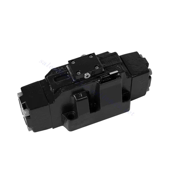
WH სერიის მიმართულებითი ჰიდრავლიკური სარქველები სითხის მუშაობით

WH სერიის მიმართულების მქონე ჰიდრავლიკური სარქველები სითხის მუშაობით წარმოადგენს ულტრათანამედროვე გადაწყვეტას ჰიდრავლიკურ სისტემებში სითხის ზუსტი კონტროლისა და ეფექტური მართვის მისაღწევად. ეს სარქველები დაპროექტებულია მოწინავე სითხის ტექნოლოგიით და გთავაზობთ გამორჩეულ მუშაობას, საიმედოობას და მრავალფეროვნებას.
WH სერიის მიმართული ჰიდრავლიკური სარქველები სითხის მუშაობით რევოლუციური კომპონენტებია, რომლებიც უზრუნველყოფენ ჰიდრავლიკურ სისტემებში სიზუსტეს, ეფექტურობას და საიმედოობას. მათი სითხის მუშაობით, განსაკუთრებული მიმართულების კონტროლით, მაღალი ნაკადის ტევადობითა და კომპაქტური დიზაინით, ეს სარქველები გთავაზობთ სხვადასხვა ინდუსტრიაში მოთხოვნილ მუშაობასა და მრავალფეროვნებას. რეკომენდებული გამოყენების მეთოდებისა და რეგულარული მოვლის პრაქტიკის დაცვით, WH სერიის სარქველები გააგრძელებენ განსაკუთრებული შედეგების მიღწევას. განაახლეთ თქვენი ჰიდრავლიკური სისტემა WH სერიის მიმართული ჰიდრავლიკური სარქველებით სითხის მუშაობით და გამოსცადეთ ზუსტი კონტროლისა და ეფექტური სითხის მართვის უპირატესობები.
WH სერიის მიმართულებითი ჰიდრავლიკური სარქველები სითხის მუშაობით. ძირითადი მახასიათებლები:
- სითხისებრი ოპერაცია:
- WH სერიის სარქველები იყენებენ სითხისებრ მუშაობას, რაც აუმჯობესებს მათ რეაგირებას და მართვის სიზუსტეს.
- ეს ინოვაციური ტექნოლოგია სარქველებს საშუალებას აძლევს უზრუნველყონ სითხის ნაკადის ზუსტი კონტროლი, რაც უზრუნველყოფს ოპტიმალურ მუშაობას სხვადასხვა დანიშნულებაში.
- მიმართულების კონტროლი:
- ეს ჰიდრავლიკური სარქველები გამოირჩევიან ჰიდრავლიკური სითხის ზუსტი მიმართულების კონტროლის უზრუნველყოფით.
- ოპერატორებს შეუძლიათ მარტივად მართონ სითხის ნაკადი და მიმართონ იგი ჰიდრავლიკური სისტემის სხვადასხვა აქტივატორზე ან კომპონენტზე.
- მაღალი ნაკადის ტევადობა:
- WH სერიის სარქველები შექმნილია მაღალი ნაკადის სიჩქარისთვის, რაც მათ შესაფერისს ხდის იმ აპლიკაციებისთვის, რომლებიც მოითხოვს სითხის მნიშვნელოვან ნაკადს.
- მათი ოპტიმიზებული შიდა გასასვლელები და მყარი კონსტრუქცია უზრუნველყოფს წნევის მინიმალურ ვარდნას და სითხის ეფექტურ მართვას.
- კომპაქტური და სივრცის დამზოგავი დიზაინი:
- ამ სარქველებს აქვთ კომპაქტური დიზაინი, რაც საშუალებას იძლევა მარტივად დამონტაჟდეს და ინტეგრირდეს ჰიდრავლიკურ სისტემებში შეზღუდული სივრცით.
- მათი სივრცის დამზოგავი დიზაინი არ ამცირებს მუშაობას, რაც მათ იდეალურს ხდის იმ აპლიკაციებისთვის, სადაც ზომა შეზღუდვას წარმოადგენს.
WH სერიის მიმართულებითი ჰიდრავლიკური სარქველები სითხის ოპერირების პარამეტრით:
WH სერიის მიმართულებითი ჰიდრავლიკური სარქველები სითხის მუშაობით უპირატესობები:
NG6-L6X
• პირდაპირი სოლენოიდის მართვის სლაიდერი სარქველი
• სამონტაჟო ზედაპირი შეესაბამება DIN 24340 A, ISO 4401 და CETOP-RP 121H ქვეფირფიტის სამონტაჟო შეერთებას ქვეფირფიტის სამონტაჟო შეერთებას
• სველი კონტაქტური ცვლადი ან მუდმივი დენის სოლენოიდები მოსახსნელი ხვეულით
• შეცვალეთ კოჭა ზეთის გამოყოფის გარეშე
• ელექტრო შეერთება ინდივიდუალური ან ცენტრალური შეერთების სახით
NG10-L3X
• პირდაპირი სოლენოიდის მართვის სლაიდერი სარქველი
• სამონტაჟო ზედაპირი შეესაბამება DIN 24340 A, ISO 4401 და CETOP-RP 121H ქვეფირფიტის სამონტაჟო შეერთებას ქვეფირფიტის სამონტაჟო შეერთებას
• DC სოლენოიდი მოსახსნელი ხვეულით.
• შეცვალეთ კოჭა ზეთის გამოყოფის გარეშე
NG10-L5X
• პირდაპირი სოლენოიდის მართვის სლაიდერი სარქველი
• სამონტაჟო ზედაპირი შეესაბამება DIN 24340 A, ISO 4401 და CETOP-RP 121H ქვეფირფიტის სამონტაჟო შეერთებას ქვეფირფიტის სამონტაჟო შეერთებას
• მუდმივი ან ცვლადი დენის სოლენოიდი მოსახსნელი კოჭათი (ცვლად დენთან შესაერთებლად გამსწორებლის გამოყენებით)
• სოლენოიდის კოჭას შეუძლია 90°-ით ბრუნვა
• კოჭას შეცვლა არ საჭიროებს დალუქული კამერის გახსნას
• დროის გადამრთველის მართვის ფუნქცია (არჩევითი)
WH სერიის მიმართულების ჰიდრავლიკური სარქველების გამოყენების მეთოდი სითხის ოპერაციით:
- სისტემის ინტეგრაცია:
- სასურველი ნაკადის გზის და კონტროლის მოთხოვნების გათვალისწინებით, განსაზღვრეთ WH სერიის სარქველების ჰიდრავლიკურ სისტემაში დამონტაჟების ოპტიმალური ადგილმდებარეობა.
- უზრუნველყავით თავსებადობა სისტემის წნევისა და ნაკადის სპეციფიკაციებთან.
- საიმედოდ დაამონტაჟეთ სარქველები შესაბამისი სამაგრების ან სამონტაჟო აქსესუარების გამოყენებით.
- სითხის შეერთებები:
- უსაფრთხო და გაჟონვისგან თავისუფალი შეერთებებისთვის შეარჩიეთ თავსებადი ჰიდრავლიკური ფიტინგები და შლანგები.
- ინსტალაციის პროცესში დაიცავით მწარმოებლის ინსტრუქციები ბრუნვის მომენტის სწორი მნიშვნელობებისთვის.
- საიმედო დალუქვის უზრუნველსაყოფად გამოიყენეთ შესაბამისი ძაფის დალუქვის საშუალებები ან ლენტი.
- კონტროლი და რეგულირება:
- WH სერიის სარქველების სამართავად გამოიყენეთ რეკომენდებული მართვის მეთოდი, როგორიცაა მექანიკური ბერკეტები ან ელექტრო მართვის საშუალებები.
- შეცვალეთ სარქველების პარამეტრები სასურველი ნაკადის მიმართულებისა და სიჩქარის მისაღწევად, რაც უზრუნველყოფს ოპტიმალურ მუშაობას.
როგორ მუშაობს პროპორციული ჰიდრავლიკური სარქველები?
პროპორციული ჰიდრავლიკური სარქველები არის მოწინავე კომპონენტები, რომლებიც ზუსტად აკონტროლებენ სითხის ნაკადს და წნევას ჰიდრავლიკურ სისტემებში. ისინი შექმნილია ჰიდრავლიკური სითხის ნაკადის სიჩქარის ან წნევის რეგულირებისთვის ელექტრო ან მექანიკური შემავალი სიგნალის პროპორციულად. აქ მოცემულია პროპორციული ჰიდრავლიკური სარქველების მუშაობის მიმოხილვა:
- სტრუქტურა:
- პროპორციული ჰიდრავლიკური სარქველები შედგება სარქვლის კორპუსის, კოჭის და სოლენოიდის ან სხვა მოქმედების მექანიზმისგან.
- სარქვლის კორპუსი შეიცავს ნაკადის გასასვლელებს და კამერებს, რომლებიც აკონტროლებენ ჰიდრავლიკური სითხის ნაკადს.
- კოჭა არის სარქვლის კორპუსში არსებული მოძრავი ელემენტი, რომელიც არეგულირებს ნაკადის გასასვლელების ზომას და პოზიციას.
- მოქმედების მექანიზმი:
- ელექტრო ან მექანიკური შეყვანის სიგნალი ააქტიურებს პროპორციულ სარქველებს.
- ყველაზე გავრცელებული გააქტიურების მექანიზმი არის სოლენოიდი, რომელიც წარმოადგენს ელექტრომაგნიტურ ხვეულს, რომელიც ენერგიის მიღებისას წარმოქმნის მაგნიტურ ველს.
- შემავალი ელექტრული სიგნალი მოდულირებს სოლენოიდზე მიწოდებულ დენს, რითაც აკონტროლებს კოჭის პოზიციას.
- კოჭის პოზიცია და ნაკადის კონტროლი:
- პროპორციულ სარქველში კოჭას აქვს სხვადასხვა დაშვება და პოზიცია, რომელიც შეესაბამება სპეციფიკურ ნაკადის სიჩქარეს ან წნევის პარამეტრებს.
- შემავალი სიგნალის ცვლილებისას, სოლენოიდი არეგულირებს კოჭის პოზიციას, რითაც იცვლება ნაკადის არეალი ან ზღუდავს ნაკადის გასასვლელებს სარქვლის კორპუსში.
- ნაკადის არეალის ეს მოდულაცია განსაზღვრავს სარქველში გამავალი ჰიდრავლიკური სითხის ნაკადის სიჩქარეს ან წნევას.
- უკუკავშირის კონტროლი:
- პროპორციული ჰიდრავლიკური სარქველები ხშირად აღჭურვილია უკუკავშირის მექანიზმებით ზუსტი კონტროლის უზრუნველსაყოფად.
- უკუკავშირის სენსორები, როგორიცაა პოზიციის ან წნევის სენსორები, რეალურ დროში გვაწვდიან ინფორმაციას სარქვლის პოზიციის ან სითხის წნევის შესახებ სარქვლის ქვემოთ.
- ეს უკუკავშირის მონაცემები ადარებს სასურველ დაყენებულ წერტილს სარქვლის ფაქტობრივ პოზიციასთან ან წნევასთან, რაც საშუალებას იძლევა დახურული ციკლის კონტროლისა და ზუსტი რეგულირების.
- მართვის ელექტრონიკა:
- პროპორციული ჰიდრავლიკური სარქველები საჭიროებენ მართვის ელექტრონიკას შემავალი სიგნალის ინტერპრეტაციისთვის, სოლენოიდის მართვისთვის და უკუკავშირის სიგნალების მისაღებად.
- მართვის ელექტრონიკა შეიძლება მოიცავდეს მიკროკონტროლერს ან ელექტრონულ სქემას, რომელიც შემავალ სიგნალს გარდაქმნის სოლენოიდის შესაბამის მართვის სიგნალებად.
- მართვის ელექტრონიკა ასევე ამუშავებს უკუკავშირის სიგნალებს და რეგულირდება სასურველი ნაკადის სიჩქარის ან წნევის შესანარჩუნებლად.
- აპლიკაციის სპეციფიკური ფუნქციონალობა:
- პროპორციული ჰიდრავლიკური სარქველების მორგება შესაძლებელია დამატებითი ფუნქციებითა და ფუნქციონალურობით კონკრეტული აპლიკაციებისთვის.
- ზოგიერთ სარქველს შეიძლება ჰქონდეს ჩაშენებული წნევის კომპენსატორები, ნაკადის სიჩქარის ლიმიტები ან სხვა მართვის სისტემებთან ინტეგრაცია.
- ეს დამატებითი მახასიათებლები საშუალებას იძლევა უფრო ზუსტი და მორგებული ჰიდრავლიკური სისტემის კონტროლისა კონკრეტული მოთხოვნების საფუძველზე.
ქარხნის შესაძლებლობები და სიმძლავრე:
(1) აწყობა
ჩვენ გვაქვს პირველი კლასის დამოუკიდებელი კვლევისა და განვითარების აწყობის პლატფორმა. ჰიდრავლიკური ცილინდრების წარმოების სახელოსნოს აქვს ოთხი ნახევრად ავტომატური ამწევი ცილინდრების აწყობის ხაზი და ერთი ავტომატური დახრილი ცილინდრების აწყობის ხაზი, რომელთა წლიური წარმოების მოცულობა 1 მილიონი ცალია. სპეციალური ცილინდრების სახელოსნო აღჭურვილია სხვადასხვა სპეციფიკაციის ნახევრად ავტომატური საწმენდი აწყობის სისტემით, რომლის წლიური წარმოების მოცულობა 200,000 ცალია და აღჭურვილია ცნობილი CNC დამუშავების აღჭურვილობით, დამუშავების ცენტრით, მაღალი სიზუსტის ცილინდრების დამუშავების სპეციალური აღჭურვილობით, რობოტ-შედუღების დანადგარით, ავტომატური საწმენდი დანადგარით, ავტომატური ცილინდრების აწყობის დანადგარით და ავტომატური შეღებვის წარმოების ხაზით. არსებული კრიტიკული აღჭურვილობა 300-ზე მეტი კომპლექტით (კომპლექტით) შედგება. აღჭურვილობის რესურსების ოპტიმალური განაწილება და ეფექტური გამოყენება უზრუნველყოფს პროდუქციის სიზუსტის მოთხოვნებს და აკმაყოფილებს პროდუქციის მაღალი ხარისხის საჭიროებებს.


(2) დამუშავება
დამუშავების საამქრო აღჭურვილია ინდივიდუალურად მორგებული დახრილი რელსების შემობრუნების ცენტრით, დამუშავების ცენტრით, მაღალსიჩქარიანი დამუშავების დანადგარით, შედუღების რობოტით და სხვა დაკავშირებული აღჭურვილობით, რომელსაც შეუძლია ცილინდრული მილების დამუშავება მაქსიმალური შიდა დიამეტრით 400 მმ და მაქსიმალური სიგრძით 6 მეტრი.


(3) შედუღება


(4) შეღებვა და საფარი
მცირე და საშუალო ზომის ცილინდრიანი ავტომატური წყალზე დაფუძნებული საღებავის საფარის ხაზებით, ავტომატური რობოტის ჩატვირთვა-გადმოტვირთვისა და ავტომატური შესხურების მისაღწევად, ცვლაში 4000 ცალი დიზაინის ტევადობით;
ჩვენ ასევე გვაქვს ელექტრო ჯაჭვით მომუშავე ნახევრად ავტომატური საღებავის წარმოების ხაზი დიდი ცილინდრებისთვის, ცვლაში 60 ყუთის დამუშავების საპროექტო სიმძლავრით.


(5) ტესტირება
ჩვენ გვაქვს პირველი კლასის შემოწმების ობიექტები და სატესტო ცენტრები, რათა უზრუნველვყოთ, რომ ცილინდრის მუშაობა აკმაყოფილებს მოთხოვნებს.


ჩვენ ვართ ერთ-ერთი საუკეთესო ჰიდრავლიკური ცილინდრების მწარმოებელი. ჩვენ შეგვიძლია შემოგთავაზოთ ჰიდრავლიკური ცილინდრების ყოვლისმომცველი ნაკრები. ჩვენ ასევე ვთავაზობთ შესაბამის... სასოფლო-სამეურნეო გადაცემათა კოლოფიჩვენ ჩვენი პროდუქცია მსოფლიოს მასშტაბით კლიენტებისთვის ექსპორტირებული გვაქვს და კარგი რეპუტაცია დავიმსახურეთ ჩვენი უმაღლესი ხარისხისა და გაყიდვის შემდგომი მომსახურების წყალობით. ჩვენ მივესალმებით როგორც ადგილობრივ, ასევე საზღვარგარეთელ მომხმარებლებს, რომლებიც დაგვიკავშირდებიან ბიზნესთან დაკავშირებით მოლაპარაკებების, ინფორმაციის გაცვლისა და ითანამშრომლეთ ჩვენთან!