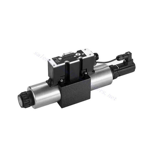
4WRE(E) 시리즈 비례 방향 유압 밸브
유압 실린더 제조업체, 공급 업체 및 기계 제품 수출 업체 중 하나로서 유압 실린더 및 기타 여러 제품을 제공합니다.
자세한 내용은 당사에 문의해 주세요.
메일:sales@hydraulic-cylinders.net
유압 실린더 제조업체 공급 업체 수출.
4WRE(E) 시리즈 비례 방향 유압 밸브
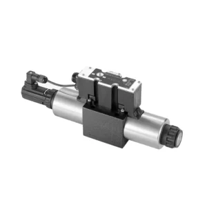
The 4WRE(E) series proportional directional hydraulic valve is a cutting-edge hydraulic component designed to deliver precise control and exceptional performance in hydraulic systems. This valve utilizes advanced proportional control technology to ensure accurate flow regulation and seamless directional changes.
The 4WRE(E) series proportional directional hydraulic valve empowers hydraulic systems with precise flow control, versatile directional changes, and energy efficiency. Its proportional control technology enables accurate and responsive flow adjustment, while the high flow capacity ensures reliable performance even in demanding applications. By following the recommended usage methods and maintenance guidelines, you can maximize the benefits and longevity of the 4WRE(E) series valve, elevating your hydraulic system to new levels of precision and performance. Upgrade your hydraulic setup today and experience the power of the 4WRE(E) series proportional directional hydraulic valve.
4WRE(E) Series Proportional Directional Hydraulic Valve Key Characteristics:
- Proportional Control Technology:
- The 4WRE(E) series valve features advanced proportional control technology, allowing for precise and proportional flow adjustment according to control signals.
- This feature enables accurate and responsive control, resulting in improved system performance and efficiency.
- 다양한 방향 제어:
- With its proportional directional control capability, this valve offers versatile control over hydraulic fluid direction.
- It allows for seamless activation and deactivation of hydraulic components such as cylinders, motors, and actuators in different directions, enhancing system flexibility and productivity.
- 고유량 용량:
- The 4WRE(E) series valve is designed to handle high flow rates, making it suitable for applications requiring substantial hydraulic power.
- 견고한 구조로 까다로운 조건에서도 안정적인 성능을 보장하며, 일관되고 효율적인 흐름 제어를 제공합니다.
- 에너지 효율성:
- By employing advanced flow control mechanisms, this valve minimizes pressure drops and optimizes energy usage.
- 이는 에너지 소비를 줄이는 데 도움이 되어 비용을 절감하고 환경에도 도움이 됩니다.
4WRE(E) Series Proportional Directional Hydraulic Valve Parameter:
| 유압 | ||||
| 설치 위치 | 선택 사항, 가급적 수평 | |||
| 크기 | 6 | 10 | ||
| 무게 | 4WRE…L2X | 킬로그램 | 2.2 | 6.3 |
| 4WREE…L2X | 2.4 | 6.5 | ||
| Nominal flow qnom at Δp = 10 bar | 리터/분 | 8 16 32 | 25 50 75 | |
| 히스테리시스 | % | ≤0.1 | ||
| Reversal span | % | ≤0.05 | ||
| 반복성 | % | ≤0.05 | ||
| 최대 작동 압력 | 포트 s ABP | 술집 | 315 | |
| 포트 T | 술집 | 210 | ||
| 체액 | NBR 및 FKM 씰에 적합한 미네랄 오일 | |||
| FKM 씰용 인산 에스테르 | ||||
| Ambient air temperature range | 4WRA…L2X | ℃ | -20℃ to 70℃ (-4°F to 158°F) | |
| 4WRAE…L2X | ℃ | -20℃ to 50℃ (-4°F to 122°F) | ||
| 점도 범위 | mm²/초 | 20~380(가급적 30~46) | ||
| 오염 정도 | NAS1638 클래스 9 또는 ISO 4406 클래스 20/18/15 | |||
| 전기 데이터 | ||||
| 1)솔레노이드 | ||||
| 크기 | 6 | 10 | ||
| 전압 유형 | 직류 | |||
| 명령값 신호 | ±10V 또는 4~20mA | |||
| Max.current per solenoid | 에이 | 2.5 | ||
| 코일 저항 | 차가운 값 | 오메가 | 2.7 | 3.7 |
| 최대 따뜻함 값 | 4.05 | 5.55 | ||
| 의무 | % | ED 100% | ||
| 코일 온도 | ℃ | 150 | ||
| EN 60529에 따른 밸브 보호 | IP 65 | |||
| 2) Control electronics | ||||
| 앰프 | 4WRE…L2X | VT-VSPA2-L2X | ||
| 4WREE…L2X | integrated(OBE) | |||
| 작동 전압 | 정격 전압 | VDC | 24 | |
| 하한값 | 다섯 | 19.4 | ||
| 상한값 | 다섯 | 35 | ||
| 증폭기 전류 소비 | 아이맥스 | 에이 | < 2 | |
| 아이맥스 | 에이 | 3 | ||
4WRE(E) Series Proportional Directional Hydraulic Valve Advantages:
• 직접 작동 비례 방향 밸브는 액체 흐름의 흐름과 방향을 제어하는 데 사용됩니다.
• 패널형 설치
• 비례 솔레노이드는 나사 연결을 통해 밸브 코어를 작동시키고 코일은 별도로 제거할 수 있습니다.
• Spool position feedback
• 내장 앰프 옵션, 4WRAE…L2X 유형 입력은 A1 또는 F1이 가능합니다.
• 외부 앰프 공급 지원
Usage Method Of 4WRE(E) Series Proportional Directional Hydraulic Valve:
- 시스템 평가:
- 유압 시스템을 평가하고 특정 흐름 및 방향 제어 요구 사항을 파악합니다.
- Determine if the 4WRE(E) series valve is suitable based on its flow capacity, pressure rating, and compatibility with your system.
- 밸브 선택:
- Select the appropriate variant of the 4WRE(E) series valve based on your system parameters, flow requirements, and directional control needs.
- 최대 유량, 압력 등급, 응답 시간, 작동 조건 등의 요소를 고려하세요.
- 설치:
- 제조업체의 설치 지침을 주의 깊게 따르고 밸브가 올바르게 정렬되고 안전하게 장착되도록 하세요.
- Make leak-free connections and ensure correct flow direction alignment to guarantee optimal performance.
- 제어 신호 연결:
- 밸브의 제어 신호선을 비례 증폭기나 전자 제어 장치와 같은 적절한 제어 장치에 연결합니다.
- 정확하고 반응성 있는 제어를 위해 밸브와 제어 장치 간의 적절한 배선과 호환성을 확보하세요.
How To Adjust Valves With Hydraulic Lifters?
유압 리프터의 밸브 래시 조정은 엔진 성능을 유지하고 밸브 소음이나 출력 저하와 같은 문제를 예방하는 데 중요한 유지 관리 작업입니다. 유압 리프터의 밸브 래시 조정 방법에 대한 단계별 가이드는 다음과 같습니다.
- 준비:
- 조정 과정을 시작하기 전에 엔진이 꺼져 있고 식었는지 확인하세요.
- 엔진의 점화 순서와 엔진 모델에 대해 제조업체가 제공한 특정 밸브 래시 사양을 숙지하세요.
- 올바른 실린더를 식별하세요:
- 엔진의 점화 순서도를 참조하여 엔진의 점화 위치를 찾으세요.
- 조정하려는 특정 밸브에 해당하는 실린더를 식별하세요.
- 실린더 위치:
- 소켓 렌치나 엔진에 내장된 회전 장치를 사용하여 엔진 크랭크샤프트를 수동으로 돌립니다.
- 조정하려는 실린더를 압축 행정의 상사점(TDC)에 위치시키세요. 크랭크샤프트 풀리의 타이밍 마크를 정렬하거나 피스톤 스톱 도구를 사용하면 됩니다.
- 로커 암을 풀어줍니다.
- 조정하려는 특정 밸브의 로커 암을 찾으세요.
- 적절한 렌치나 소켓을 사용하여 로커 암 너트나 조절 나사를 풀어줍니다.
- 밸브 래시 조정:
- 로커 암이 느슨해졌으므로 이제 밸브 래시를 조정할 수 있습니다. 밸브 래시는 로커 암과 밸브 스템 사이의 간격입니다.
- 필러 게이지를 사용하여 기존 밸브 래시를 측정합니다. 로커 암과 밸브 스템 사이에 적절한 두께 게이지를 삽입합니다.
- 간격이 너무 좁으면 필러 게이지가 맞지 않거나 과도한 저항이 발생하므로 밸브 래시를 늘려야 합니다. 간격이 너무 좁으면 필러 게이지가 너무 쉽게 밀려 들어가므로 밸브 래시를 줄여야 합니다.
- 밸브 래시를 조정하려면 로커 암 너트 또는 조정 나사를 적절히 조이거나 풀어야 합니다. 권장 조정량은 제조업체의 사양을 참조하십시오.
- 밸브 래시를 다시 확인하세요.
- 조정을 한 후에는 필러 게이지를 사용하여 밸브 래시를 다시 확인하여 권장 사양 내에 있는지 확인하세요.
- 필요한 경우 올바른 밸브 래시가 달성될 때까지 조정 과정을 반복합니다.
- 다른 실린더에 대해서도 반복합니다.
- 발사 순서에 따라 다음 실린더로 진행하고 조정하려는 각 실린더에 대해 4~6단계를 반복합니다.
- 밸브 래시를 조정하기 전에 크랭크샤프트를 회전시키고 압축 행정에서 각 실린더를 상사점에 위치시키는 것을 잊지 마세요.
- 로커 암을 고정하세요:
- 각 실린더의 밸브 래시를 적절히 조정한 후, 로커 암 너트 또는 조정 나사를 제조업체에서 권장하는 토크 사양에 따라 조입니다.
- 조인 후 밸브 래시가 지정된 범위 내에 있는지 다시 한번 확인하세요.
- 최종 점검:
- 엔진 크랭크샤프트를 몇 번 돌려서 부드럽게 회전하는지 확인하고, 이상한 소음이나 저항이 있는지 확인하세요.
- 엔진을 시동하고 밸브에서 이상한 소리가 나는지 들어보세요. 과도하게 두드림이나 노킹이 들리면 밸브 래시 조정을 다시 확인하세요.
공장의 역량 및 용량:
(1) 조립
당사는 최고 수준의 독자적인 연구개발 조립 플랫폼을 보유하고 있습니다. 유압 실린더 생산 작업장은 4개의 반자동 리프팅 실린더 조립 라인과 1개의 자동 틸트 실린더 조립 라인을 갖추고 있으며, 연간 100만 개의 설계 생산 능력을 갖추고 있습니다. 특수 실린더 작업장은 다양한 사양의 반자동 세척 조립 시스템을 갖추고 있으며, 연간 20만 개의 설계 생산 능력을 갖추고 있습니다. 또한, 유명 CNC 가공 장비, 머시닝 센터, 고정밀 실린더 가공 특수 장비, 로봇 용접기, 자동 세척기, 자동 실린더 조립기, 자동 도장 생산 라인을 갖추고 있습니다. 300대 이상의 핵심 장비를 보유하고 있으며, 장비 자원의 최적 배치 및 효율적인 사용을 통해 제품의 정밀성 요구 사항을 충족하고 고품질 요구를 충족합니다.


(2) 가공
가공공장은 맞춤형 경사레일 터닝센터, 가공센터, 고속 호닝머신, 용접로봇 및 기타 관련 장비를 갖추고 있으며, 최대 내경 400mm, 최대 길이 6m의 원통형 튜브를 가공할 수 있습니다.

(3) 용접

(4) 도장 및 코팅
소형, 중형 실린더 자동 수성 페인트 코팅 라인을 통해 자동 로봇 로딩 및 언로딩과 자동 분무를 실현하며, 교대당 4000개의 설계 용량을 달성합니다.
또한, 우리는 60개의 케이스를 교대로 생산할 수 있는 설계 용량을 갖춘 파워 체인으로 구동되는 대형 실린더용 반자동 페인트 생산 라인을 보유하고 있습니다.


(5) 테스트
당사는 실린더의 성능이 요구 사항을 충족하는지 확인하기 위해 일류 검사 시설과 테스트 베드를 갖추고 있습니다.

저희는 최고의 유압 실린더 제조업체 중 하나입니다. 다양한 유압 실린더를 공급할 수 있으며, 관련 제품도 제공합니다. 농업용 기어박스저희는 전 세계 고객에게 제품을 수출해 왔으며, 탁월한 제품 품질과 애프터서비스를 통해 좋은 평판을 얻고 있습니다. 국내외 고객 여러분의 사업 상담, 정보 교환, 그리고 우리와 협력하다!
유압 실린더 응용 분야:
